
Hard multilayer coating, hard multilayer coated tool including the hard multilayer coating, and method of forming the hard multilayer coating

a multi-layer coating and hard coating technology, applied in the field of hard multi-layer coating, can solve the problems of insufficiently preventing chipping and separation, insufficiently showing excellent wear resistance of tialn, etc., and achieve excellent adhesiveness or bonding strength, excellent wear resistance, and high hardness.

Inactive Publication Date: 2006-03-07
OSG
View PDF27 Cites 27 Cited by
  • Summary
  • Abstract
  • Description
  • Claims
  • Application Information

AI Technical Summary

Benefits of technology

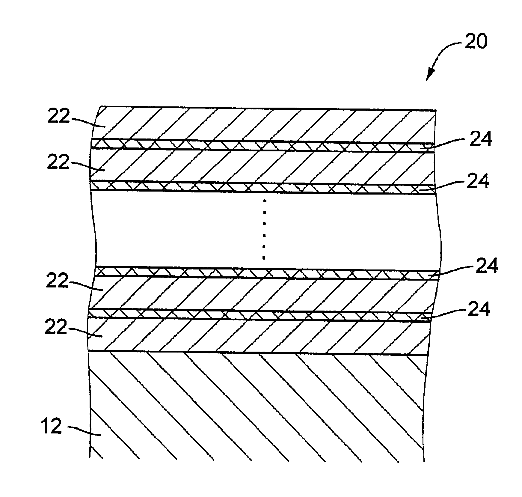
[0017]In the hard multilayer coating defined in the first aspect of the invention, (Tix Al1-x) (Cy N1-y) (wherein 0.20≦x≦0.60, 0≦y≦0.5) constituting the first coating layer has a hardness (Hv) of about 2300-3000, while CrN constituting the second coating layer has a hardness (Hv) of about 1800-2000. Thus, the hard multilayer coating, in which the first coating layer having the relatively high degree of hardness and the second coating layer having the relatively low degree of hardness are alternately superposed on each other, has a tenacity which is increased owing to the presence of the second coating layer having the relatively low degree of hardness, so that the hard multilayer coating does not easily suffer from chipping and separation from the substrate. Further, since CrN is not oxidized unless CrN is heated to have a high temperature of about 700° C., the presence of CrN does not deteriorate a heat resistance of the hard multilayer coating. Still further, since the outermost or uppermost layer of the hard multilayer coating is constituted by the first coating layer having the relatively high degree of hardness, the hard multilayer coating has an excellent wear resistance.
[0018]The hard multilayer coating defined in the second aspect of the invention, in which the innermost or lowermost layer is constituted by the first coating layer, can be bonded to the substrate with an excellent adhesiveness or bonding strength.
[0019]In the hard multilayer coating defined in the third aspect of the invention, the first coating layers has an average thickness of 10-2000 nm while the second coating layer has an average thickness of 10-1000 nm, and the hard multilayer coating has a total thickness of 0.5-20 μm. These dimensional features of the third aspect of the invention is effective to assure prevention of chipping and separation of the multilayer coating owing to the presence of the second coating layer while maintaining wear resistance owing to the presence of the first coating layer.
[0020]In the hard multilayer coating defined in the fourth aspect of the invention in which the second coating layer has a composition of mixture of the CrN and (Tix Al1-x) (Cy N1-y) (wherein 0.20≦x≦0.60, 0≦y≦0.5), the second coating layers is bonded to the first coating layers with a higher degree of adhesiveness or bonding strength than where the second coating layer is constituted only by the CrN, whereby chipping and separation of the multilayer coating are more reliably prevented.
[0021]The hard multilayer coated tool defined in the fifth aspect of the invention provides substantially the same technical advantages as the first through fourth aspects of the invention, and has an improved durability or prolonged service life.
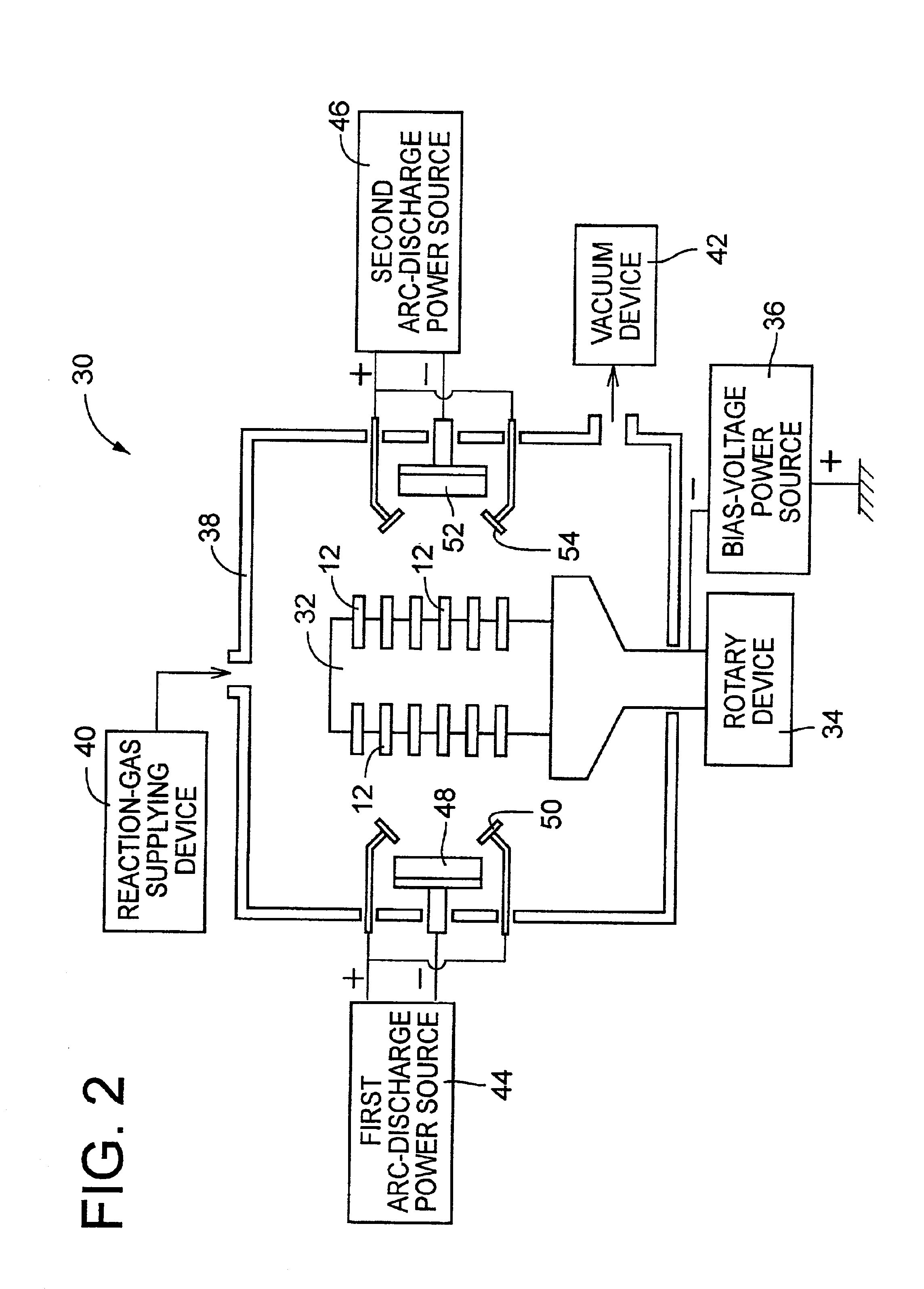
[0022]In the method defined in the sixth aspect of the invention, the formation of the first coating layer and the formation of the second coating layer are alternated with each other by switching on and off the first and second arc-discharge power sources, and the thickness of each of the coating layers is adjusted by controlling the arc current supplied from the corresponding arc-discharge power-source and / or the power-on time of the corresponding arc-discharge power source, so that each of the coating layers can be formed to have a desired thickness with high precision.

Problems solved by technology

However, since the TiAlN hard coating has a poor tenacity due to a large internal stress therein, the hard coating is likely to be chipped or separated from the tool substrate during a cutting operation, thereby making it impossible to sufficiently exhibit an excellent wear resistance of TiAlN.
The provision of an interface layer or the superposing of two types of TiAlN hard coating layers which are different from each other in their mixed crystal proportions might somewhat prevents the chipping and separation, but does not satisfactorily prevents the chipping and separation.

Method used


Image

  • Hard multilayer coating, hard multilayer coated tool including the hard multilayer coating, and method of forming the hard multilayer coating
  • Hard multilayer coating, hard multilayer coated tool including the hard multilayer coating, and method of forming the hard multilayer coating
  • Hard multilayer coating, hard multilayer coated tool including the hard multilayer coating, and method of forming the hard multilayer coating

Examples


Embodiment Construction

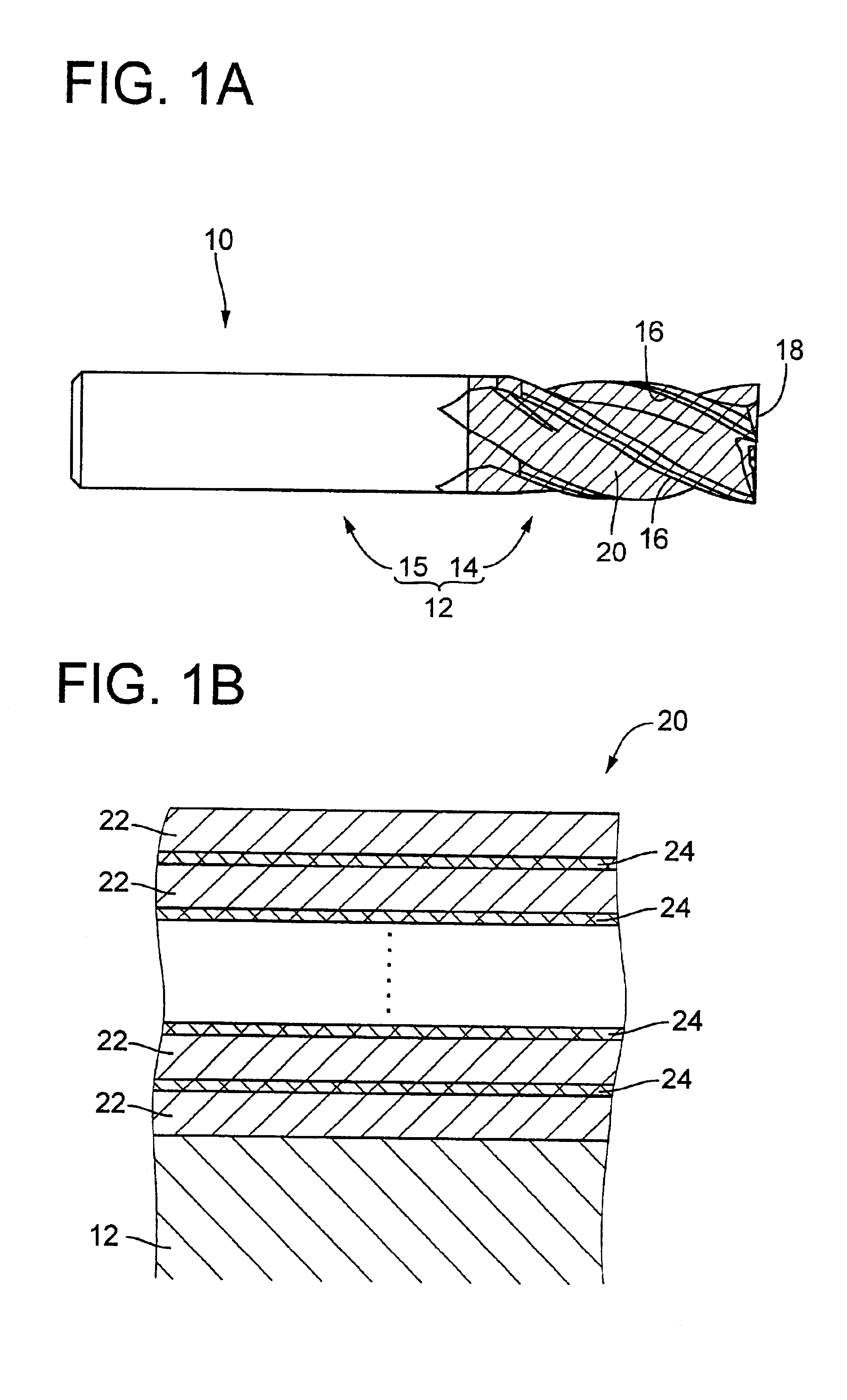
[0042]FIG. 1A is an elevational view of a hard multilayer coated tool in the form of an end mill 10 which is constructed according to an embodiment of the invention. The end mill 10 includes a tool substrate (base material) 12 having a generally cylindrical shape and formed of a cemented carbide. The tool substrate 12 has a cutting teeth portion 14 and a shank portion 15 which are formed integrally with each other. The cutting teeth portion 14, in which helical flutes and cutting teeth are formed, has a surface that is coated with a hard multilayer coating 20. In FIG. 1A, the oblique-lined portion represents a portion of the surface on which the hard multilayer coating 20 is coated. Each of the cutting teeth has a peripheral flank face, a bottom or end flank face and a rake face which is provided by the corresponding one of the helical flutes, so that a peripheral cutting edge 16 and a bottom or end cutting edge 18 are formed in each cutting tooth. The peripheral cutting edge 16 is ...


PUM

PropertyMeasurementUnit
total thicknessaaaaaaaaaa

Abstract

A hard multilayer coating which is to be disposed on a surface of a substrate, including at least one first coating layer and at least one second coating layer which are alternately superposed on each other, wherein each of the at least one first coating layer consists of (Tix Al1-x) (Cy N1-y) wherein 0.20≦x≦0.60, 0≦y≦0.5, while each of the at least one second coating layer includes CrN, and wherein one of the at least one first coating layer constitutes an outermost layer of the hard multilayer coating.

Description

BACKGROUND OF THE INVENTION[0001]1. Field of the Invention[0002]The present invention relates in general to a hard multilayer coating, and more particularly to such a hard multilayer coating having excellent wear resistance and tenacity.[0003]2. Discussion of the Related Art[0004]There is known a coated tool in which a tool substrate made of a cemented carbide or other material is coated at its surface with a hard coating formed of TiAlN. As an example of such a coated tool, JP-A-10-168583 (publication of unexamined Japanese Patent Application laid open in 1998) discloses a tool in which an interface layer formed of a relatively soft material such as CrN is interposed between the tool substrate and the hard coating formed of TiAlN, for the purpose of increasing a degree of adhesive or bonding strength with which the hard coating is bonded to the tool substrate. Further, JP-A-11-216601 (publication of unexamined Japanese Patent Application laid open in 1999) discloses a hard multilay...

Claims


Application Information

Patent Timeline
Patent Type & Authority Patents(United States)
IPC IPC(8): B32B9/00B23C5/16B23B27/14B23B51/00B23C5/10B23P15/28B32B18/00C04B35/56C04B35/58C04B35/581C23C14/06C23C28/04C23C30/00
CPCB23C5/10C23C14/0641C23C30/005C23C28/044C23C14/0664B23C2224/24Y10T428/265Y10T428/24975
Inventor TOIHARA, TAKAOMI
Owner OSG
Learn More