Method and apparatus for displaying image by producing polarization inversion in ferroelectric member and producing contrast in contrast production member

a technology of ferroelectric components and production members, applied in the field of image display media, can solve the problems of high energy consumption, inability to control the electric circuit, and inability to drive the above-mentioned image display apparatus,

Inactive Publication Date: 2006-03-07
FUJIFILM HLDG CORP +1
View PDF5 Cites 1 Cited by
  • Summary
  • Abstract
  • Description
  • Claims
  • Application Information

AI Technical Summary

Benefits of technology

[0007]An object of the present invention is to provide a method for displaying an image by using an inexpensive arrangement in such a manner that the displayed image is maintained without application of a voltage.
[0008]Another object of the present invention is to provide an apparatus which is inexpensive and can display an image in such a manner that the displayed image is maintained without application of a voltage.
[0009]A further object of the present invention is to provide an image display medium on which an image can be displayed by using an inexpensive arrangement in such a manner that the displayed image is maintained without application of a voltage.
[0070](b) The inorganic ferroelectric oxides exhibits much higher heat durability than the organic polymer materials such as polyvinylidene fluoride. Therefore, when the ferroelectric member is made of an inorganic ferroelectric oxide, reliable image display is realized.

Problems solved by technology

Therefore, the above manner of driving an image display apparatus is disadvantageous for reduction of energy consumption.
However, in the above liquid crystal display apparatus, an image is basically displayed by using a liquid crystal panel, which is expensive.
Further, an expensive electric circuit is necessary for controlling the voltage application to the liquid crystal panel for each pixel.
Therefore, manufacturing cost is high.

Method used


Image

  • Method and apparatus for displaying image by producing polarization inversion in ferroelectric member and producing contrast in contrast production member
  • Method and apparatus for displaying image by producing polarization inversion in ferroelectric member and producing contrast in contrast production member
  • Method and apparatus for displaying image by producing polarization inversion in ferroelectric member and producing contrast in contrast production member

Examples


first embodiment

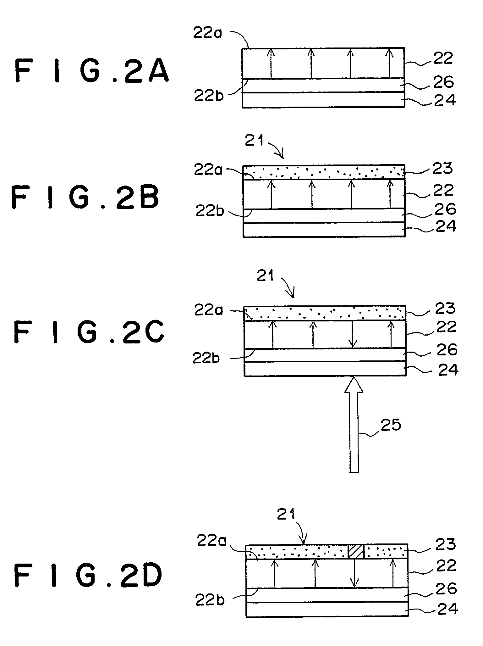
[0112]The first embodiment of the present invention is explained below with reference to FIGS. 2A to 2D. FIG. 2A shows a cross section of a portion of the image display medium in the first embodiment of the present invention, and FIGS. 2B to 2D show a cross section of the image display medium in the first embodiment of the present invention in three stages in a process for displaying an image according to the first aspect of the present invention. The image display medium in the first embodiment of the present invention is used for displaying a monochrome image.

[0113]In FIGS. 2A to 2D, reference numeral 21 denotes the image display medium, 22 denotes a Z-cut LiNbO3 substrate (hereinafter referred to as an LN substrate), 23 denotes a contrast production member, 24 denotes a transparent conductive film, 25 denotes infrared laser light, and 26 denotes a light-to-heat conversion film.

[0114]As illustrated in FIG. 2A, in order to produce the image display medium 21, the light-to-heat conv...

second embodiment

[0126]The second embodiment of the present invention is explained below with reference to FIGS. 3A to 3D. FIG. 3A shows a cross section of a portion of the image display medium in the second embodiment of the present invention, and FIGS. 3B to 3D show a cross section of the image display medium in the second embodiment of the present invention in three stages in a process for displaying an image according to the first aspect of the present invention. The image display medium in the second embodiment of the present invention is also used for displaying a monochrome image. In FIGS. 3A to 3D, elements having the same reference numbers as FIGS. 2A to 2D have the same functions as the corresponding elements in FIGS. 2A to 2D, and only the differences from the first embodiment are explained below.

[0127]In FIGS. 3A to 3D, reference numeral 31 denotes the image display medium, 22 denotes a Z-cut LiNbO3 substrate (LN substrate), 32 denotes a contrast production member, 24 denotes a transpare...

third embodiment

[0138]The third embodiment of the present invention is explained below with reference to FIG. 5, which is a diagram illustrating a cross section of a portion of the image display medium in the third embodiment of the present invention. In FIG. 5, the contrast production member 32 is not illustrated. The image display medium in the third embodiment of the present invention is also used for displaying a monochrome image. In FIG. 5, elements having the same reference numbers as FIG. 3A have the same functions as the corresponding elements in FIG. 3A, and only the differences from the second embodiment are explained below.

[0139]The image display medium in the third embodiment of the present invention is different from the image display medium in the second embodiment in that a light-to-heat conversion film 26 is provided instead of the periodical light-to-heat conversion film 36, and a periodically-transparent conductive film 34 is provided instead of the transparent conductive film 24....


PUM

PropertyMeasurementUnit
frequencyaaaaaaaaaa
thicknessaaaaaaaaaa
surface chargeaaaaaaaaaa

Abstract

In a method for displaying an image: a polarization inversion pattern is produced in a ferroelectric member in accordance with image information so as to produce a surface charge pattern corresponding to the polarization inversion pattern; and an image contrast is produced in a contrast production member by the influence of the surface charge pattern, where the contrast production member is joined to the ferroelectric member. The polarization inversion pattern may be produced by heating the ferroelectric member so as to produce a heat distribution corresponding to the image information in the ferroelectric member. Further, the ferroelectric member may be heated by applying infrared light carrying the image information to the ferroelectric member.

Description

BACKGROUND OF THE INVENTION[0001]1. Field of the Invention[0002]The present invention relates to a method for displaying an image by using a ferroelectric material. In addition, the present invention relates to an apparatus for executing the above method. Further, the present invention relates to an image display medium which is used in the method.[0003]2. Description of the Related Art[0004]The liquid crystal display apparatus is one of the currently known image display apparatuses. In most of the liquid crystal display apparatuses currently used, a display signal applied to each pixel is updated at a predetermined frame frequency, e.g., 60 Hz. When an image display apparatus is driven in this manner, a voltage is required to be continuously applied to each pixel even when a still image is displayed. Therefore, the above manner of driving an image display apparatus is disadvantageous for reduction of energy consumption.[0005]In order to solve the above problem, a liquid crystal dis...

Claims


Application Information

Patent Timeline
Patent Type & Authority Patents(United States)
IPC IPC(8): G03G5/16G02F1/03G02F1/01G02F1/135G02F1/1524G02F1/163H04N5/66H04N9/12
CPCG02F1/0126G02F1/167G02F1/1358G02F2202/07G02F1/163G02F1/3558G02F1/15165G02F1/1524
Inventor NIHEI, YASUKAZU
Owner FUJIFILM HLDG CORP
Why Eureka
Try Eureka