
Method for monitoring objects with transponders

a technology of transponders and objects, applied in the direction of instruments, resonant antennas, burglar alarm mechanical actuation, etc., can solve problems such as not always being the case, and achieve the effect of reducing interferen

Inactive Publication Date: 2006-03-07
GLAXO GROUP LTD
View PDF141 Cites 171 Cited by
  • Summary
  • Abstract
  • Description
  • Claims
  • Application Information

AI Technical Summary

Benefits of technology

[0010]A principal advantage of the present invention is the capability of the memory of the RFID tag to store many environmental data items which are written to the memory at various defined points in the manufacturing-distribution-storage process. The memory thereby provides a detailed and readily accessible ‘environmental exposure’ history. The environmental information could, for example, also include date and time stamps. The memory might also be configured to include a unique serial number stored in encrypted form or in a password protectable part of the memory which uniquely identifies the product. The information could also include basic product information such as the nature of the product and usage information, customer information and distribution information such as the intended product destination.
[0011]The use of RFID tags to monitor environmental exposure is known in the art. Thus GB 2308947 discloses RFID tags having sensors incorporated within the transponder which can transmit environmental data to a remote reader on energising therefrom. Similar devices relating to RFID tags possessing built-in sensors are described for biomedical GB 2297225 and agricultural GB 2249001, GB 2076259 applications.
[0012]The principal advantages of the Applicant's invention over those disclosed in the literature are those of simplicity and cost. By eliminating the need to build individual sensors into each tag the Applicant's have devised a simplified method of monitoring environmental exposure at significantly reduced cost to the user.SUMMARY OF THE INVENTION
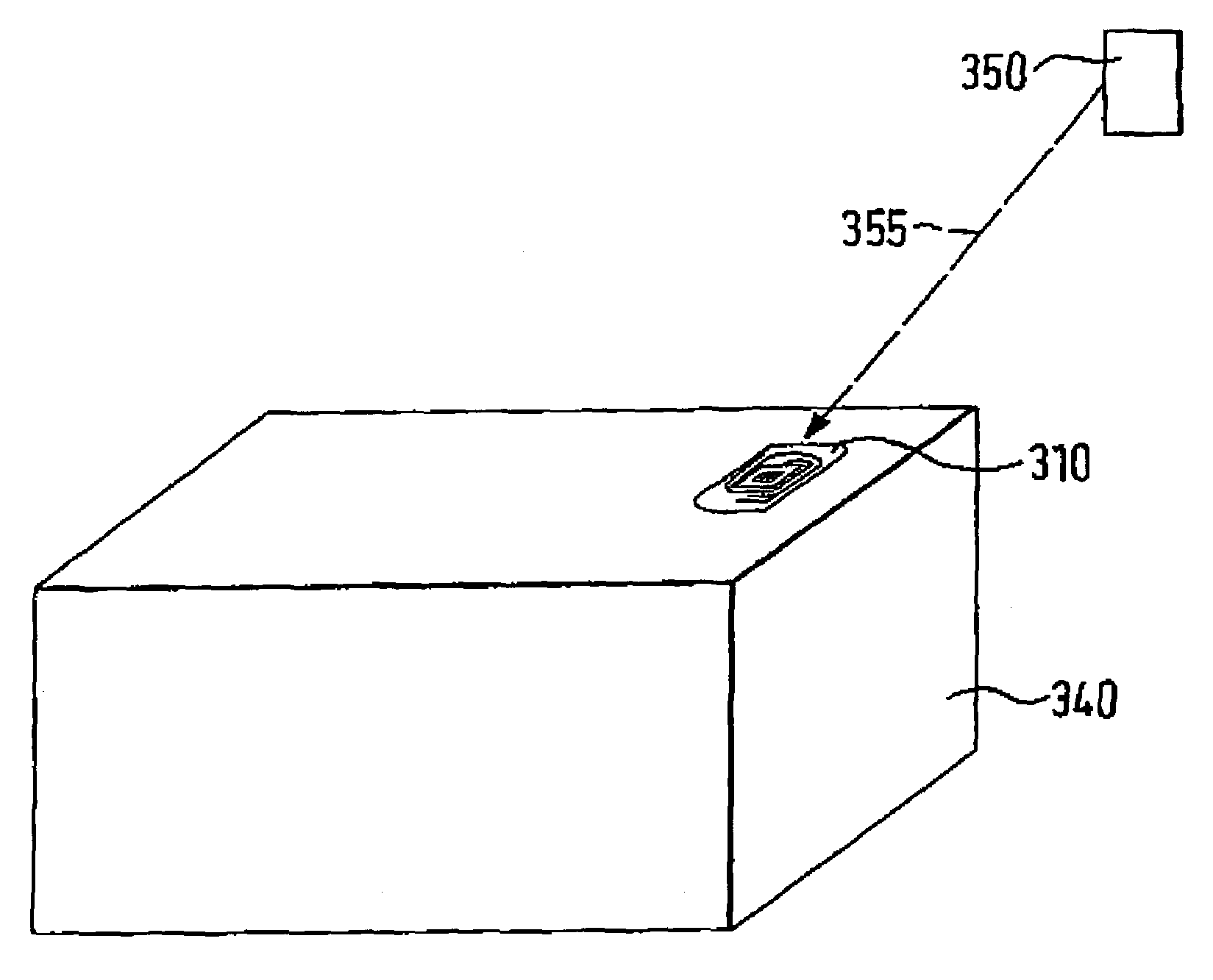
[0013]According to one aspect of the present invention there is provided a method for tracking environmental exposure of an object comprising selecting an object; associating a radiofrequency identifier with the object, the radiofrequency identifier comprising an antenna for transmitting or receiving radiofrequency energy; and an integrated circuit chip connecting with the antenna, the chip having a memory; exposing the object to an environmental condition; measuring the environmental condition as an environmental parameter with a sensor physically separate from the radiofrequency identifier; and writing the environmental parameter to the memory of the chip by transmitting radiofrequency energy thereto.
[0014]The object may be exposed to environmental conditions throughout its lifetime. Whilst environmental conditions are likely to be stringently controlled during the manufacturing process this is not always necessarily the case in all industries and in all manufacturing localities. Variation in environmental conditions are most likely during product transport and storage; for example, transport at reduced temperatures and pressures during air freight, or on delivery to storage depots in the tropics.
[0015]The radiofrequency identifier can be any known radiofrequency identifier. Such identifiers are sometimes known as radiofrequency transponders or radiofrequency identification tags. Suitable radiofrequency identifiers include those sold by Phillips Semiconductors of the Netherlands under the trade marks Hitag, and Icode those sold by Amtech Systems Corporation of the United States of America under the trade mark Intellitag, and those sold by Texas Instruments of the United States of America under the trade mark Tagit.

Problems solved by technology

Whilst environmental conditions are likely to be stringently controlled during the manufacturing process this is not always necessarily the case in all industries and in all manufacturing localities.

Method used


Image

  • Method for monitoring objects with transponders
  • Method for monitoring objects with transponders
  • Method for monitoring objects with transponders

Examples


Embodiment Construction

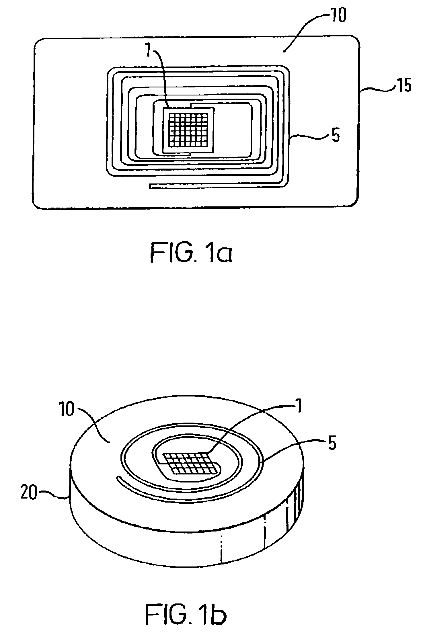
[0083]The basic components of an RFID tag are shown in FIGS. 1a and 1b. The tag comprises a memory chip 1 which is capable of storing, transmitting and receiving information and an antenna 5. Data can be received by, or transmitted from, the chip via antenna 5 which is connected to the chip. The antenna 5, is capable of receiving or transmitting radiofrequency energy over a wide bandwidth, ranging from 50 KHz to 2.5 GHz. The tags 10 are mounted on a rectangular 15 (FIG. 1a) or disc 20 (FIG. 1b) shaped carrier. The carrier, which generally comprises an insulating material such as glass, may take several forms such as a flexible label (FIG. 1a), a rectangular block or a rigid disc (FIG. 1b).

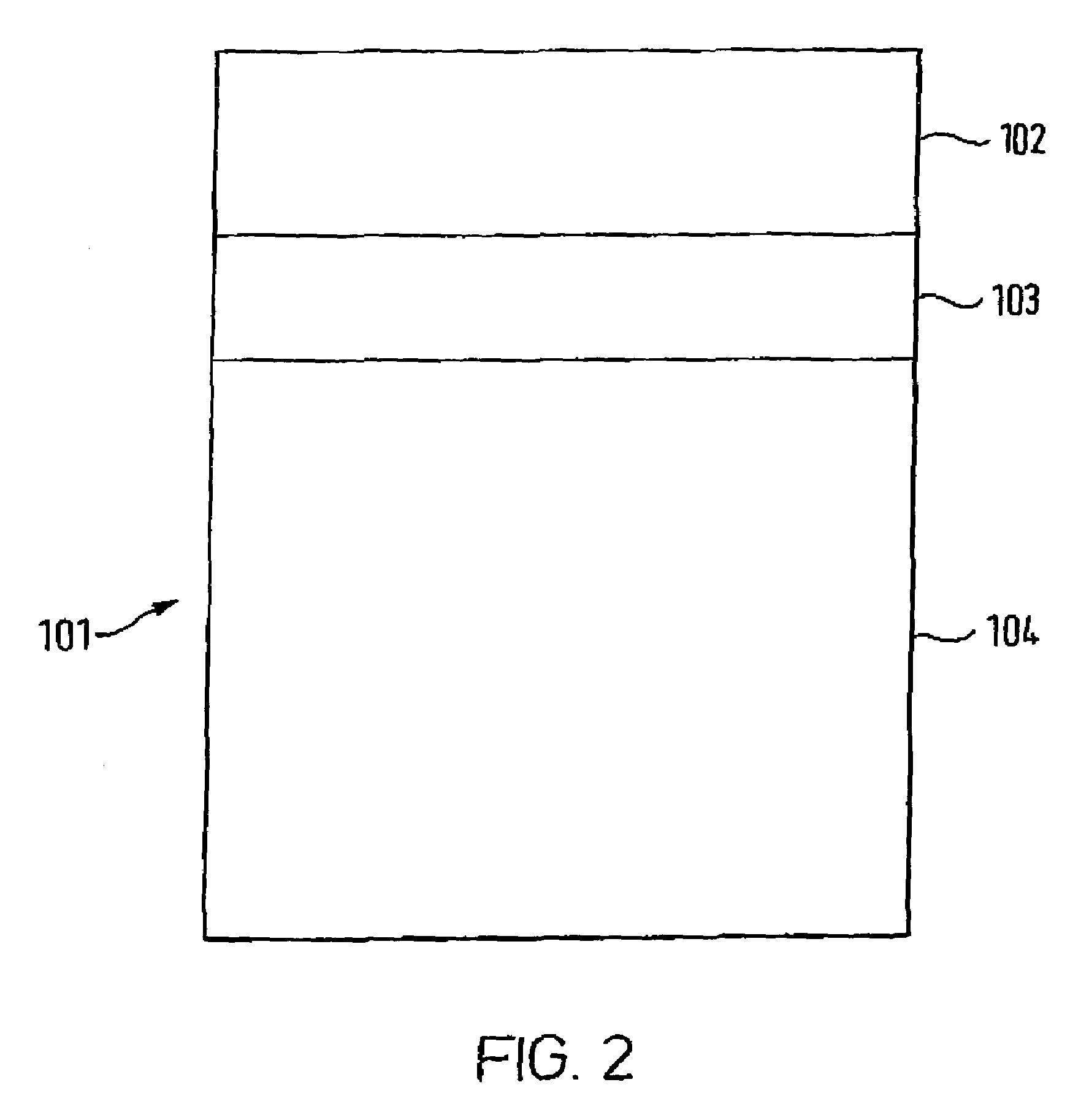
[0084]FIG. 2 is a schematic representation of the memory structure of the RFID chip 101. Such tags are divided into unique blocks, typically numbering sixteen in total, with data being stored in non-volatile memory EEPROM, the EEPROM having a memory capacity of 512 bits with each block consisting o...


PUM


Abstract

There is provided a method for tracking environmental exposure of an object comprising selecting the object; associating a radiofrequency identifier with the object, the radiofrequency identifier comprising an antenna for transmitting or receiving radiofrequency energy; and an integrated circuit chip connecting with said antenna, said chip having a memory; exposing the object to an environmental condition; measuring environmental condition as an environmental parameter with a sensor physically separate from the radiofrequency identifier; and writing the environmental parameter to the memory of the chip by transmitting radiofrequency energy thereto.

Description

CROSS REFERENCE TO RELATED APPLICATION[0001]This application is filed pursuant to 35 USC 371 as a United States National Phase Application of International Patent Application Serial No. PCT / EP01 / 04972 filed May 2, 2001, which claims priority from GB 0012465.1 filed on May 24, 2000 in the United Kingdom.FIELD OF THE INVENTION[0002]The present invention relates to a method of monitoring exposure of an object to environmental conditions. In particular, it relates to a method of tracking environmental exposure of medicaments and medical devices to a range of environmental conditions using radio frequency identification tags.BACKGROUND OF THE INVENTION[0003]Exposure to environmental conditions, such as temperature, moisture and pressure, can have a marked effect upon the storage or shelf life of many products. Many chemicals and biological products, for example those used in medicaments, are sensitive to changes in temperature and / or moisture, with relatively small variations in either l...

Claims


Application Information

Patent Timeline
IPC IPC(8): G08B13/14H01Q1/38G06K19/07G08C17/02H01Q1/22H01Q9/30
CPCG06K19/0717G08C17/02G06K19/0723
Inventor WOOD, CHRISTOPHER IVOR
Owner GLAXO GROUP LTD
Learn More