Path search circuit for simultaneously performing antenna directivity control and path search
- Summary
- Abstract
- Description
- Claims
- Application Information
AI Technical Summary
Benefits of technology
Problems solved by technology
Method used
Image

Examples
1st embodiment
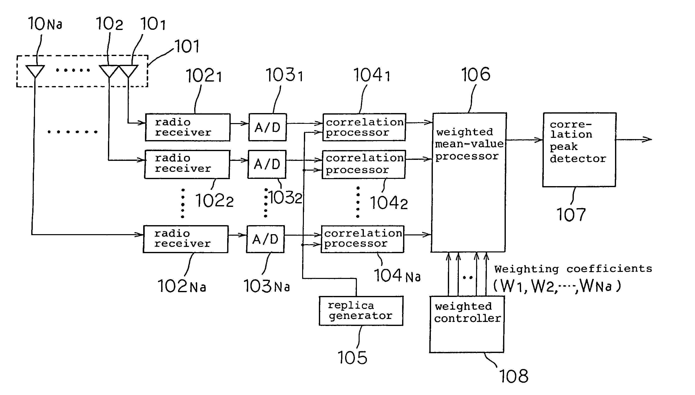
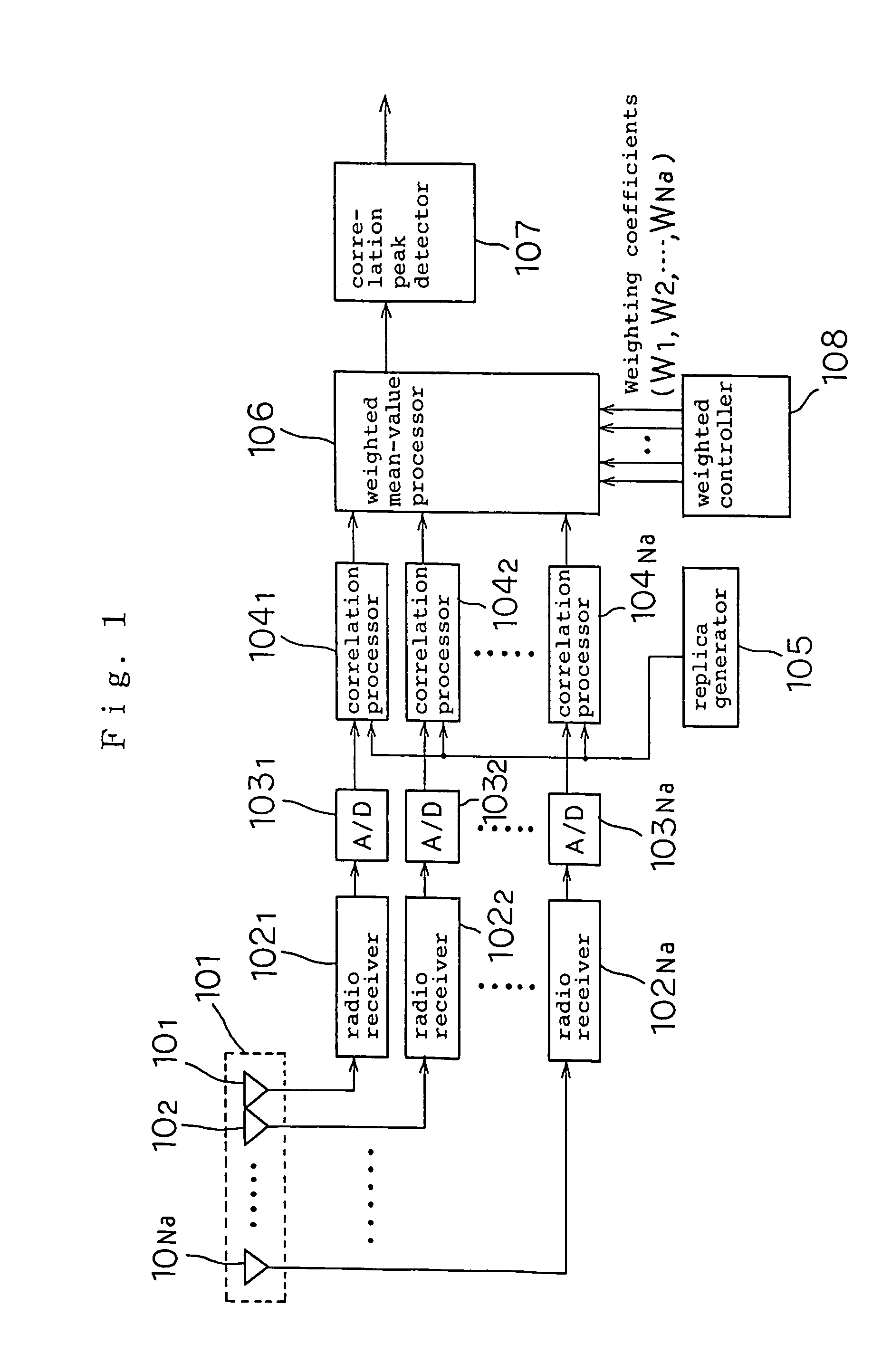
[0036]Referring now to FIG. 1, there is shown a path search circuit according to a first embodiment of the present invention which comprises an array antenna 101 having Na antenna elements 101–10Na that are arranged as a linear array at half wavelength intervals, Na radio receivers 1021–102Na connected respectively to the antenna elements 101–10Na, Na A / D converters 1031–103Na connected respectively to the radio receivers 1021–102Na, a replica generator 105, Na correlation processors 1041–104Na connected respectively to the A / D converters 1031–103Na and the replica generator 105, a weighted-mean-value processor 106 connected to the correlation processors 1041–104Na, a correlation peak detector 107 connected to the weighted-mean-value processor 106, and a weighting controller 108 connected to the weighted-mean-value processor 106.
[0037]The A / D converters 1031–103Na converts received signals supplied from the radio receivers 1021–102Na into digital data. The replica generator 105 gene...
2nd embodiment
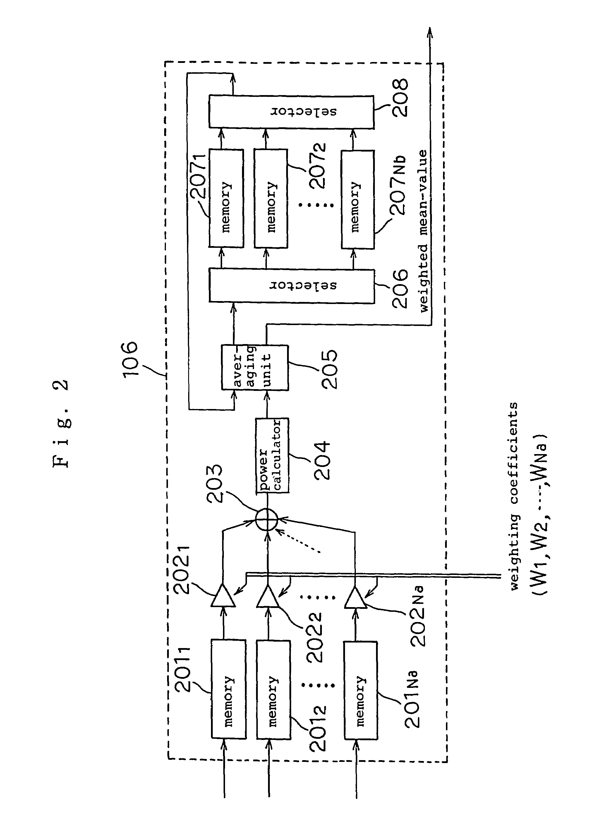
[0078]A path search circuit according to a second embodiment of the present invention will be described below. The path search circuit according to the second embodiment is similar to the path search circuit according to the first embodiment except that it has a weighted-mean-value processor 106a shown in FIG. 4, rather than the weighted-mean-value processor 106. Those parts of the weighted-mean-value processor 106a which are identical to those of the weighted-mean-value processor 106 are denoted by identical reference characters and will not be described in detail below.
[0079]The weighted-mean-value processor 106a shown in FIG. 4 differs from the weighted-mean-value processor 106 shown in FIG. 2 in that it has an interpolation filter 301 between the adder 203 and the power calculator 204, and a multiplier 302 between the selector 208 and the averaging unit 205.
[0080]The interpolation filter 301 samples again the weighted correlation signal output form the adder 203 at a frequency h...
PUM
 Abstract
Description
Claims
Application Information