Light-beam switching/adjusting apparatus and manufacturing method thereof

a technology of switching/adjusting apparatus and manufacturing method, which is applied in the field of light beams, can solve the problems of difficult alignment of light guide substrate and actuator substrate, and easy damage of mirrors, so as to achieve easy discrimination of insertion position of insertion plates inside the slits, and the effect of reducing the number of insertions

Inactive Publication Date: 2006-03-07
NIKON CORP +1
View PDF26 Cites 0 Cited by
  • Summary
  • Abstract
  • Description
  • Claims
  • Application Information

AI Technical Summary

Benefits of technology

[0019]The present invention was devised in order to solve the problems described above. The first object of the present invention is to provide a light beam switching and adjustment device which can be manufactured easily and with a good yield as a result of the alignment of the mirrors and mirror receiving recesses being facilitated, and a method for manufacturing this light beam switching and adjustment device. Furthermore, the second object of the present invention is to provide a light beam switching and adjustment device in which discrimination of the positional relationship between the insertion plates and the slits formed in the light guide cores, and the discrimination of the insertion positions of the insertion plates inside the slits, are easy.
[0113]These first through thirtieth inventions make it possible to provide light beam switching and adjustment devices that can be manufactured easily and with a good yield, and manufacturing methods for the same, in accordance with the respective inventions. Furthermore, these inventions can provide light beam switching and adjustment devices that allow a reduction in the size of the device and facilitate inspections and the like in the manufacturing process. Furthermore, the matter of which of these effects is obtained by which invention will be clear from the constructions of the inventions described above and the embodiments described later.
[0118]These thirty-first and thirty-second inventions make it possible to provide a light beam switching and adjustment device in which discrimination of the positional relationship between the insertion plates and the slits disposed in the light guide cores is easy. Furthermore, in addition to this, the thirty-third invention makes it possible to provide a light beam switching and adjustment device in which discrimination of the insertion positions of the insertion plates inside the slits is easy.

Problems solved by technology

However, in the actual performance of such alignment, it has been ascertained that this alignment is extremely difficult.
Furthermore, if the mirrors collide with parts other than the mirror receiving recesses in the process of this alignment of the mirrors relative to the mirror receiving recesses, the mirrors are easily damaged.
Accordingly, the alignment of the light guide substrate and actuator substrate is extremely difficult.
Especially in cases where the number of mirrors is large, all of the mirrors must be aligned with the corresponding mirror receiving recesses; accordingly, this alignment is extremely difficult.
Accordingly, the following problem arises: namely, the presence of such constituent elements is a major obstacle to observation of the relative positional relationship between the insertion plates and the slits.
Furthermore, the following problem is also encountered: specifically, the observational magnification during microscopic observation inevitably increases according to the width of the slits and the size of the insertion plates that are the objects of observation; accordingly, the depth of field is shallow, so that it is difficult to discriminate the insertion positions of the insertion plates inside the slits.

Method used


Image

  • Light-beam switching/adjusting apparatus and manufacturing method thereof
  • Light-beam switching/adjusting apparatus and manufacturing method thereof
  • Light-beam switching/adjusting apparatus and manufacturing method thereof

Examples


Embodiment Construction

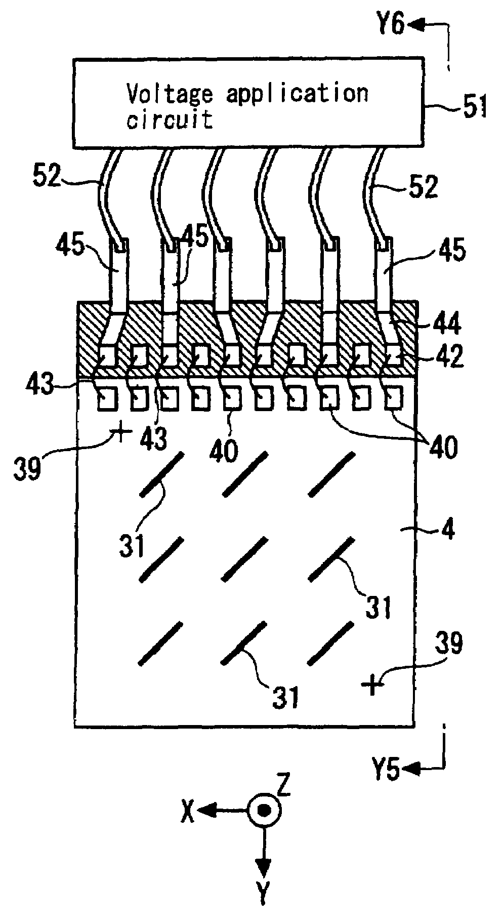
[0136]The light beam switching and adjustment device of the present invention, and method for manufacturing the same, will be described below with reference to the figures.

[0137]FIG. 1 is a schematic plan view which shows in model form a light beam switching and adjustment device according to one embodiment of the present invention. For convenience of description, mutually perpendicular X, Y and Z axes are defined as shown in FIG. 1 (these axes are the same in figures described later). Furthermore, in FIGS. 1 through 14, the same constituent elements are labeled with the same symbols, and a description for each figure may be omitted. The surface of the light guide substrate 2 and the surface of the actuator substrate 4 are parallel to the XY plane. Furthermore, for convenience of description, the + side in the direction of the Z axis (i.e., the side toward which the arrow is oriented) will be referred to as the +Z side, and the − side in the direction of the Z axis will be referred ...


PUM


Abstract

The light guide substrate 2 has mirror receiving grooves 24 and light guides. The light guides conduct light that is input into the input ports to selected output ports in accordance with the advance and retraction of the mirrors 31 with respect to the grooves 24. The actuator substrate 4 has mirrors 31 and actuators which place the mirrors 31 in a state in which the mirrors are drawn in toward the substrate 4, or a state in which the mirrors protrude from the substrate 4. The light guide substrate 2 and actuator substrate 4 are aligned using alignment marks and joined with a spacer 3 interposed so that the mirrors 31 retract from the grooves 24 when the mirrors 31 are drawn in toward the substrate 4, and so that the mirrors 31 advance into the grooves 24 when the mirrors 31 protrude from the substrate 4. This alignment is performed in a state in which all of the mirrors 31 are drawn in toward the substrate 4.

Description

[0001]This application is a U.S. National Phase Application under 35 USC 371 of International Application PCT / JP02 / 13003 filed Dec. 12, 2002.TECHNICAL FIELD[0002]The present invention relates to a light beam switching and adjustment device used to perform light beam light path conversion and adjustment of the amount of transmission in (for example) optical communications networks, optical switching systems or the like, and a method for manufacturing the same.BACKGROUND ART[0003]Light beam switching and adjustment devices used for light path conversion are necessary in optical communications systems, and in recent years, matrix light beam switching and adjustment devices used to perform light path switching among a plurality of inputs and outputs have become especially important. For example, such matrix light beam switching and adjustment devices perform actions such as the transmission of light signals from one of numerous parallel input optical fibers to one of numerous parallel o...

Claims


Application Information

Patent Timeline
Patent Type & Authority Patents(United States)
IPC IPC(8): G02B6/26G02B6/35H01L25/065H04Q11/00
CPCG02B6/3596H04Q11/0005G02B6/3512G02B6/3546G02B6/357G02B6/3582H04Q2011/0058H04Q2011/003H04Q2011/0039G02B6/3584
Inventor AKAGAWA, KEIICHISUZUKI, YOSHIHIKOISHIZUYA, TOHRUSUZUKI, JUNJIKURUMADA, KATSUHIKOKANAYA, MASATOSHITAMAMURA, TOSHIAKI
Owner NIKON CORP
Why Eureka
Try Eureka