Exhaust-gas turbocharger

Inactive Publication Date: 2006-03-14
DAIMLER AG
View PDF13 Cites 32 Cited by
  • Summary
  • Abstract
  • Description
  • Claims
  • Application Information

AI Technical Summary

Benefits of technology

[0004]With the exhaust-gas turbocharger according to the invention cooling of the backside of the compressor wheel is improved.
[0005]Also the passage of compressed air from the front to the back of the compressor wheel is advantageously reduced. A so-called blow-by barrier furthermore ensures that the coolant is returned into a cooling circuit without blow-by.

Problems solved by technology

Since the compressor wheel, reaches high rotational speeds, these centrifugal forces will only permit inadequate cooling of the back of the compressor wheel.
Such bubble formation, however, leads to an unfavorable heat transmission at the back of the compressor wheel, which has an adverse effect on cooling performance.

Method used


Image

  • Exhaust-gas turbocharger
  • Exhaust-gas turbocharger
  • Exhaust-gas turbocharger

Examples


Embodiment Construction

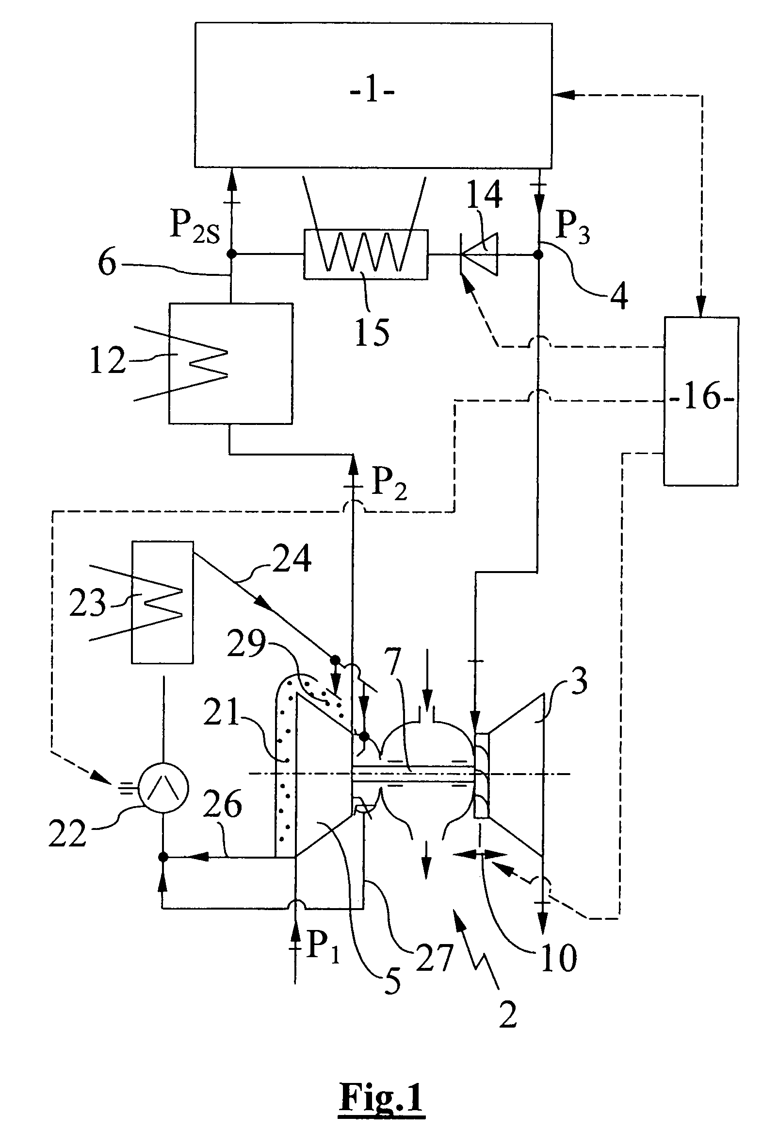
[0011]FIG. 1 shows a supercharged internal combustion engine 1, which may be a spark-ignition engine, a diesel engine or a gas engine. The internal combustion engine 1 includes an exhaust-gas turbocharger 2 with a turbine 3 in an exhaust line 4, which extends from the internal combustion engine 1, and a compressor 5 in an intake section 6 of the engine 1. A shaft 7 transmits the movement of a turbine wheel of the turbine 3 to a compressor wheel 8 of the compressor 5, whereupon fresh intake air at atmospheric pressure p1 is compressed to an increased pressure p2 in the compressor 5. The exhaust-gas turbine 3 of the exhaust-gas turbocharger 2 is provided with a variable turbine geometry 10, by means of which the effective flow inlet cross-section to the turbine wheel can be variably adjusted. The variable turbine geometry 10 takes the form, for example, of a guide vane ring with adjustable guide vanes arranged in the flow inlet cross-section of the turbine 3. It is also possible, howe...


PUM


Abstract

In an exhaust gas turbocharger including a compressor wheel, the compressor wheel is cooled by at least one nozzle which is arranged in close axial proximity to the axis of rotation of the compressor wheel for spraying the backside of the compressor wheel near the center thereof with coolant whereby the coolant, utilizing the centrifugal forces of the rotating compressor wheel, is completely distributed over the entire wheel back surfaces.

Description

BACKGROUND OF THE INVENTION[0001]The invention relates to an exhaust-gas turbocharger for an internal combustion engine with a cooled compressor wheel.[0002]An exhaust-gas turbocharger which includes an arrangement for cooling the compressor wheel of the exhaust-gas turbocharger is already known (DE 198 45 375 A1). The rear wall of the compressor wheel is cooled by introducing a coolant at a radial distance from an outer edge or outer circumference of the compressor wheel. In order to flow along the rear wall of the compressor wheel therefore, the coolant has to overcome the centrifugal forces generated by rotation of the compressor wheel. Since the compressor wheel, reaches high rotational speeds, these centrifugal forces will only permit inadequate cooling of the back of the compressor wheel. Introducing the coolant at a radial distance from the outer edge or outer circumference of the compressor wheel furthermore means that compressed air can get into the coolant through a radial...

Claims


Application Information

Patent Timeline
IPC IPC(8): F02D23/00F01D5/08F01D5/18F02C6/12F04B17/00F01D11/02F01D25/12F01D25/14F04D29/58
CPCF01D11/02F01D25/12F01D25/14F04D27/0207F04D29/681F04D29/584F05D2260/232F05D2220/40F05D2260/201F04D29/284F04D29/4206
Inventor SUMSER, SIEGFRIEDFINGER, HELMUTHEINZ, EDUARDLE CLECH, LIONELSCHMID, WOLFRAM
Owner DAIMLER AG
Why Eureka
Try Eureka