Low temperature heat engine

a heat engine and low temperature technology, applied in combination engines, machines/engines, combination engines, etc., can solve the problem that the efficient method of removing latent heat from the expansion of vapor is less efficient, and achieve the effect of less efficient method of removing latent hea

Inactive Publication Date: 2006-03-14
TERRAN TECH
View PDF18 Cites 31 Cited by
  • Summary
  • Abstract
  • Description
  • Claims
  • Application Information

AI Technical Summary

Benefits of technology

[0009]This cold liquid is expanded through a flow restricting device to a significantly lower pressure state where it is expanded isobarically and absorbs the latent heat remaining in the saturated turbine discharge vapor. In the example discussed here, the isobaric expansion occurs at 4 psia, which has an effective temperature of −60 degrees F. This vapor absorbs the remaining latent heat of condensation in the discharge of the prime mover, resulting in a complete liquefaction of the discharge. As demonstrated in the Von Linde process for atmospheric gas liquefaction, only a tiny mass fraction has to be evaporated to accomplish this effect. This can also be accomplished by expanding cold vapor as well as liquid. However, expanding vapor is a less efficient method of removing the latent heat. Further, the direct removal of the vapor in the accumulator via the suction of a compressor that discharges into the prime mover header could keep the accumulator pressure at the desired level.

Problems solved by technology

However, expanding vapor is a less efficient method of removing the latent heat.

Method used


Image

  • Low temperature heat engine
  • Low temperature heat engine
  • Low temperature heat engine

Examples


Embodiment Construction

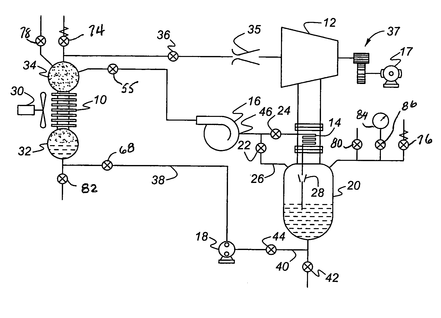
[0015]FIG. 1 illustrates a system that includes a heat exchanger 10, which functions as a boiler; a prime mover 12 such as turbine 12, which is the primary extractor of heat in the form of work; and a heat exchanger 14, which function as a cooler; and an accumulator 20, a storage vessel containing discharge fluid that has passed through the prime mover. Compressor 16 draws suction from the condensate in accumulator 20 through line 26 and valve 22 to the inlet side of the compressor. Liquid condensate, drawn by compressor 16 from accumulator 20 through an expansion device 28, expands through the expansion device 28 into a low pressure volume of heat exchanger 14, the cold side. The condensate or discharge fluid flash boils at the heat exchanger 14 and extracts latent heat from the discharge fluid leaving turbine 12. The expanded vapor is then scavenged by compressor 16, which maintains low pressure in accumulator 20, is compressed to a higher pressure, and is injected into a steam dr...


PUM


Abstract

A method for producing power to drive a load (17) using a working fluid circulating through a system that includes a prime mover (12) having an inlet and an accumulator (20) containing discharge fluid exiting the prime mover. A stream of heated vaporized fluid is supplied at relatively high pressure to the prime mover inlet and is expanded through the prime mover (12) to a lower pressure discharge side where discharge fluid enters an accumulator (20). The discharge fluid is vaporized by passing it through an expansion device (28) across a pressure differential to a lower pressure than the pressure at the prime mover discharge side. Latent heat of condensation in the discharge fluid being discharged from the prime mover is transferred by a heat exchanger (14) to discharge fluid that has passed through the expansion device (28). Vaporized discharge fluid, to which heat has been transferred from fluid discharged from the prime mover, can be returned through a compressor (20) and vapor drum (34) to the prime mover inlet. Vaporized discharge fluid can be removed directly from the accumulator (20) by a compressor (16) where it is pressurized slightly above the pressure in the vapor drum (34), to which it is delivered directly, or it can be passed through a heat exchanger (50) where the heat from the compressed fluid is transferred to an external media after leaving the compressor (16) in route to the vapor drum (34). Liquid discharge fluid from the accumulator (20) is pumped to a boiler liquid drum (32), then to the vapor drum (34) through a heat exchanger (10). The liquid discharge fluid may be expanded through an orifice (62) to extract heat from an external source at heat exchanger (56) and discharged into the vapor drum (34) or the accumulator (20), depending on its temperature upon leaving heat exchanger (56).

Description

CROSS-REFERENCE TO RELATED APPLICATION[0001]This application claims the benefit of U.S. Provisional Patent Application Ser. No. 60 / 436,536, filed Dec. 26, 2002, the disclosure of which is incorporated herein by reference.BACKGROUND OF THE INVENTION[0002]Heat engines using air, steam, mixtures of air and steam, and other working media have been used for over a century, and most of these use a single gaseous fluid as a working medium. The steam engine, especially the steam turbine, has been the most popular and successful heat engine, and present commercial steam engines have maximum efficiencies of less than 40% in converting the energy available from fuel into shaft work. Steam engines and other workable heat engines have used an external heat sink, either by direct discharge to the environment in an open cycle or to a condenser for a closed steam cycle system. It is not necessary to use a condenser to reject this latent heat to the environment. Under certain conditions, the latent ...

Claims


Application Information

Patent Timeline
Patent Type & Authority Patents(United States)
IPC IPC(8): F01K1/00F01B21/04
CPCF01K17/005
Inventor SARANCHUK, THEODORE CHARLESMARKSBERRY, DONALD EDWARD
Owner TERRAN TECH
Why Eureka
Try Eureka