
Method of continuous casting non-oriented electrical steel strip

a technology of non-oriented electrical steel and continuous casting, which is applied in the direction of magnetic materials, electrical equipment, magnetic bodies, etc., can solve the problems of degrading the magnetic properties, reducing the and reducing the core loss and magnetic permeability of the final produ

Inactive Publication Date: 2006-03-14
CLEVELAND CLIFFS STEEL PROPERTIES INC
View PDF47 Cites 17 Cited by
  • Summary
  • Abstract
  • Description
  • Claims
  • Application Information

AI Technical Summary

Benefits of technology

The method results in non-oriented electrical steel with uniform magnetic properties in all directions, achieving low core loss and high magnetic permeability, comparable to conventional CRML and CRNO grades, while reducing manufacturing costs and complexity.

Problems solved by technology

Conversely, increasing the alloy content makes the steel more difficult to manufacture owing to the added cost of alloying and increased brittleness, particularly when large amounts of silicon are employed.
The purity of the finish rolled and annealed strip can have a significant effect on core loss since the presence of a dispersed phase, inclusions and / or precipitates can inhibit grain growth during annealing, preventing the formation of an appropriately large grain size and orientation and, thereby, producing higher core loss and lower magnetic permeability in the final product form.
Also, inclusions and / or precipitates in the finish annealed steel hinder domain wall motion during AC magnetization, further degrading the magnetic properties.
Non-oriented electrical steels are predominantly used in rotating devices, such as motors or generators, where uniform magnetic properties are desired in all directions with respect to the strip rolling direction, or where the cost of a grain oriented electrical steel is not justified.
CRML is generally used in applications where the requirement for very low core losses is difficult to justify economically.

Method used


Image

  • Method of continuous casting non-oriented electrical steel strip
  • Method of continuous casting non-oriented electrical steel strip
  • Method of continuous casting non-oriented electrical steel strip

Examples


example 1

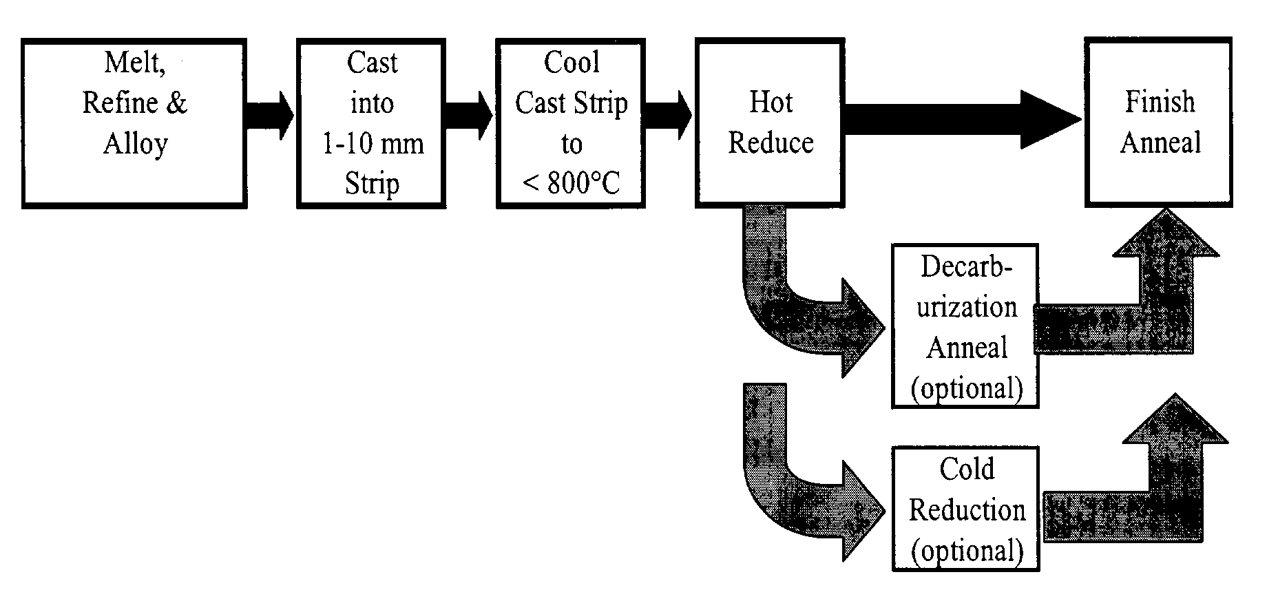
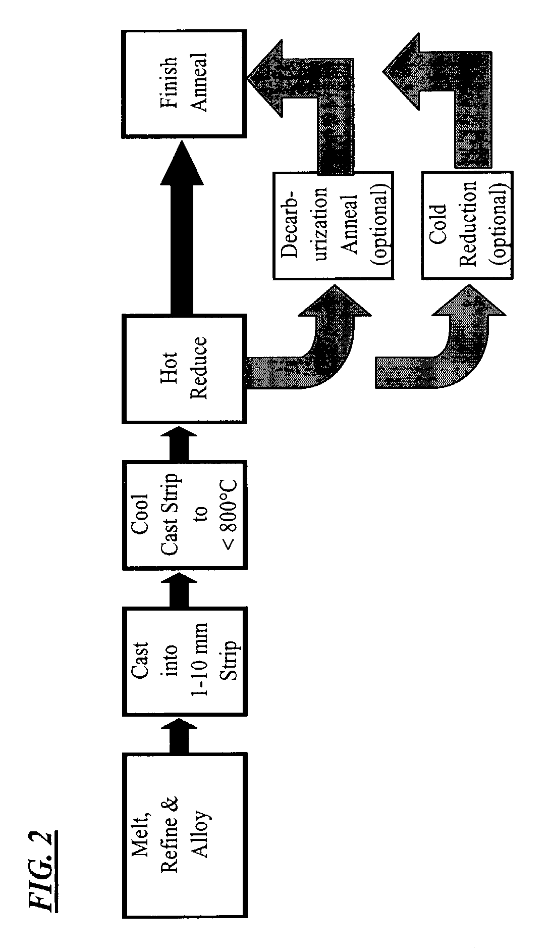
[0105]Heats A and B having the compositions shown in Table I were melted, cast into strips having a thickness of about 0.10 inch (about 2.5 mm) and processed as exemplified in FIG. 2. Cast strips from Melts A having a thickness of about 0.10 inch (about 2.5 mm) and cast strips of Heat B having a thickness of about 0.10 inch (about 2.5 mm), about 0.060 inch (about 1.5 mm) and about 0.045 inch (about 1.15 mm) were provided with a hot reduction of about 30% to about 65% to a thickness of less than 0.040″ (about 1 mm), the hot reduction made in a single rolling pass using about 9.5 inch (about 24 mm) diameter work rolls and a rolling speed of about 32 RPM, from a temperature below T20 as defined in Equation II. The cast and hot rolled strips were descaled, sheared into test samples and final annealed in a batch anneal at about 1550° F. (about 843° C.) for a soak time of about 60 minutes in an atmosphere of 80% nitrogen and 20% hydrogen with a dew point of about 75° F. (about 25° C.), or...

example 2

[0108]Melts A and B of Example 1 were processed in a different embodiment of the method of the present invention whereby the cast strips were processed as exemplified in FIG. 3. As shown in Table I, the composition of Melts A and B provide a volume resistivity (ρ) calculated from Equation I representative of an intermediate-silicon non-oriented electrical steel of the art. The cast and solidified strips were subjected to rapid secondary cooling to a temperature below about 1000° F. (about 540° C.) in accordance with the preferred method of the present invention. The cast, solidified and cooled strips were cold rolled to a thickness of about 0.018 inch (about 0.45 mm). After cold rolling, the strips were finish annealed by batch annealing at a temperature of about 1550° F. (about 843° C.) for a soak time of about 60 minutes in an atmosphere of 80% nitrogen and 20% hydrogen with a dew point of about 75° F. (about 25° C.), or finish annealed as a continuous strip anneal at a temperatur...

example 3

[0111]Melt C shown in Table I was cast into thin strips having a thickness of either about 0.8 inch (about 2.0 mm) or about 0.10 inch (about 2.5 mm) were processed as exemplified in FIG. 4. As Table I shows, the composition of Melt C provided a volume resistivity of about 37 μΩ-cm, making the steel of Melt C representative of an intermediate-silicon non-oriented electrical steel of the art. The cast and solidified strips from Melt C were further subjected to rapid secondary cooling to a temperature below about 1000° F. (about 540° C.) strip in accordance with the preferred method of the present invention. The cast, solidified and cooled strips were reheated to a temperature of 1750° F. (about 950° C.) or about 2100° F. (about 1150° C.) in a non-oxidizing atmosphere prior to hot rolling the cast strip, the hot rolling being conducted in a single pass using about 9.5 inch (about 24 cm) diameter work rolls and a rolling speed of about 32 RPM, from a temperature below T20 wt % γ as defi...


PUM

PropertyMeasurementUnit
thicknessaaaaaaaaaa
thicknessaaaaaaaaaa
thicknessaaaaaaaaaa

Abstract

Non-oriented electrical steels are widely used as the magnetic core material in a variety of electrical machinery and devices, particularly in motors where low core loss and high magnetic permeability in all directions of the strip are desired. A method for producing a non-oriented electrical steel with low core loss and high magnetic permeability provides a steel that is produced from a steel melt which is cast as a thin strip or sheet, cooled, hot rolled and / or cold rolled into a finished strip. The finished strip is further subjected to at least one annealing treatment wherein the magnetic properties are developed, making the steel strip suitable for use in electrical machinery such as motors or transformers.

Description

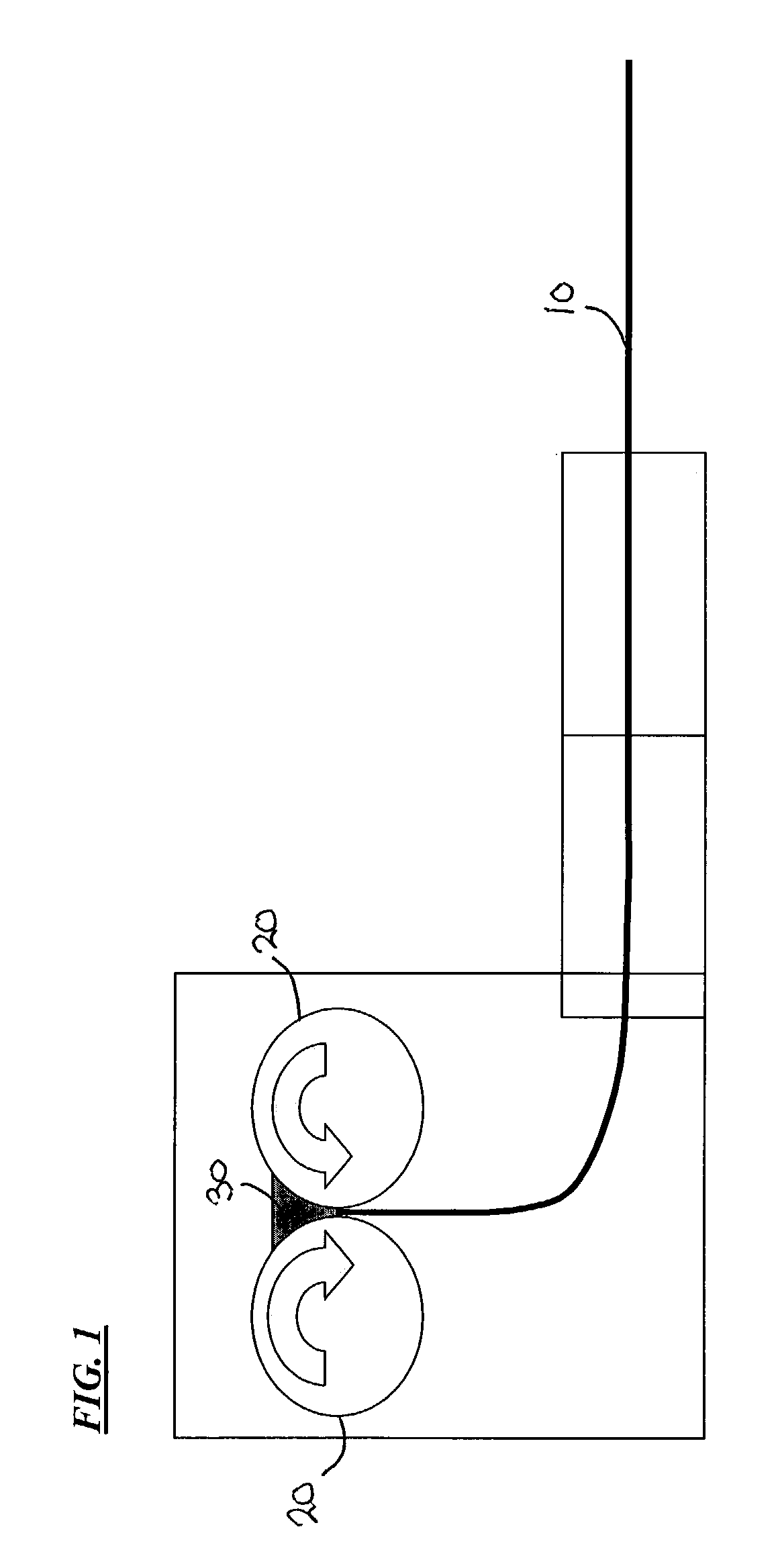
CROSS-REFERENCE TO RELATED APPLICATIONS[0001]This application claims the priority benefit of U.S. Provisional Patent Application Ser. No. 60 / 378,743, filed May 8, 2002, which application is hereby incorporated by reference in its entirety.BACKGROUND OF THE INVENTION[0002]Non-oriented electrical steels are widely used as the magnetic core material in a variety of electrical machinery and devices, particularly in motors where low core loss and high magnetic permeability in all directions of the strip are desired. The present invention relates to a method for producing a non-oriented electrical steel with low core loss and high magnetic permeability whereby the steel is produced from a steel melt which is cast as a thin strip, cooled, hot rolled and / or cold rolled into a finished strip. The finished strip is further subjected to at least one annealing treatment wherein the magnetic properties are developed, making the steel strip of the present invention suitable for use in electrical ...

Claims


Application Information

Patent Timeline
Patent Type & Authority Patents(United States)
IPC IPC(8): B22D11/00C21D8/12C22C38/38
CPCC21D8/1211C21D8/1222C21D8/1272C22C38/008C22C38/04C22C38/06C22C38/20C22C38/34C22C38/004C21D8/1233C21D8/1261C21D8/1283H01F1/14791C22C38/001C22C38/002C22C38/40C22C38/44C22C38/50
Inventor SCHOEN, JERRY W.COMSTOCK, JR., ROBERT J.
Owner CLEVELAND CLIFFS STEEL PROPERTIES INC
Learn More