Protective shield for a patient control device

a technology for protecting shields and control devices, applied in packaging goods, envelopes/bags making machinery, paper/cardboard containers, etc., can solve problems such as damage to control circuits, unpreventable contamination of nursecall devices, and easy contamination of units, so as to prolong the life of nursecall devices, reduce the need for frequent servicing, and easy insertion and removal

Inactive Publication Date: 2006-03-14
BIOTRONICS
View PDF44 Cites 404 Cited by
  • Summary
  • Abstract
  • Description
  • Claims
  • Application Information

AI Technical Summary

Benefits of technology

[0006]The present invention is directed to a shield that covers a patient control device, such as a nursecall device. In one embodiment, the shield is designed to form-fit the case of the nursecall device. Bubbles or soft elevations may be formed in the shield over buttons and/or dials on the nursecall device so they can be operated through the shield. The shield may be formed of a flexible, resilient light-passing material so that it fits snugly around the case to prevent contaminants from contacting or entering the nursecall

Problems solved by technology

Because the nursecall device can be located anywhere in the bed with the patient, the unit can easily become contaminated with various contaminants (e.g., debris, bodily excretions, bathwater, drugs, infectious bacteria and viruses, etc.).
The case is cleaned and sterilized between patients, but this does not prevent contaminants from entering the nursecall device during use.
These contaminants can damage the control circuitry, requiring the unit to be serviced.
The nursecall device often also has buttons, s

Method used


Image

  • Protective shield for a patient control device
  • Protective shield for a patient control device
  • Protective shield for a patient control device

Examples


Embodiment Construction

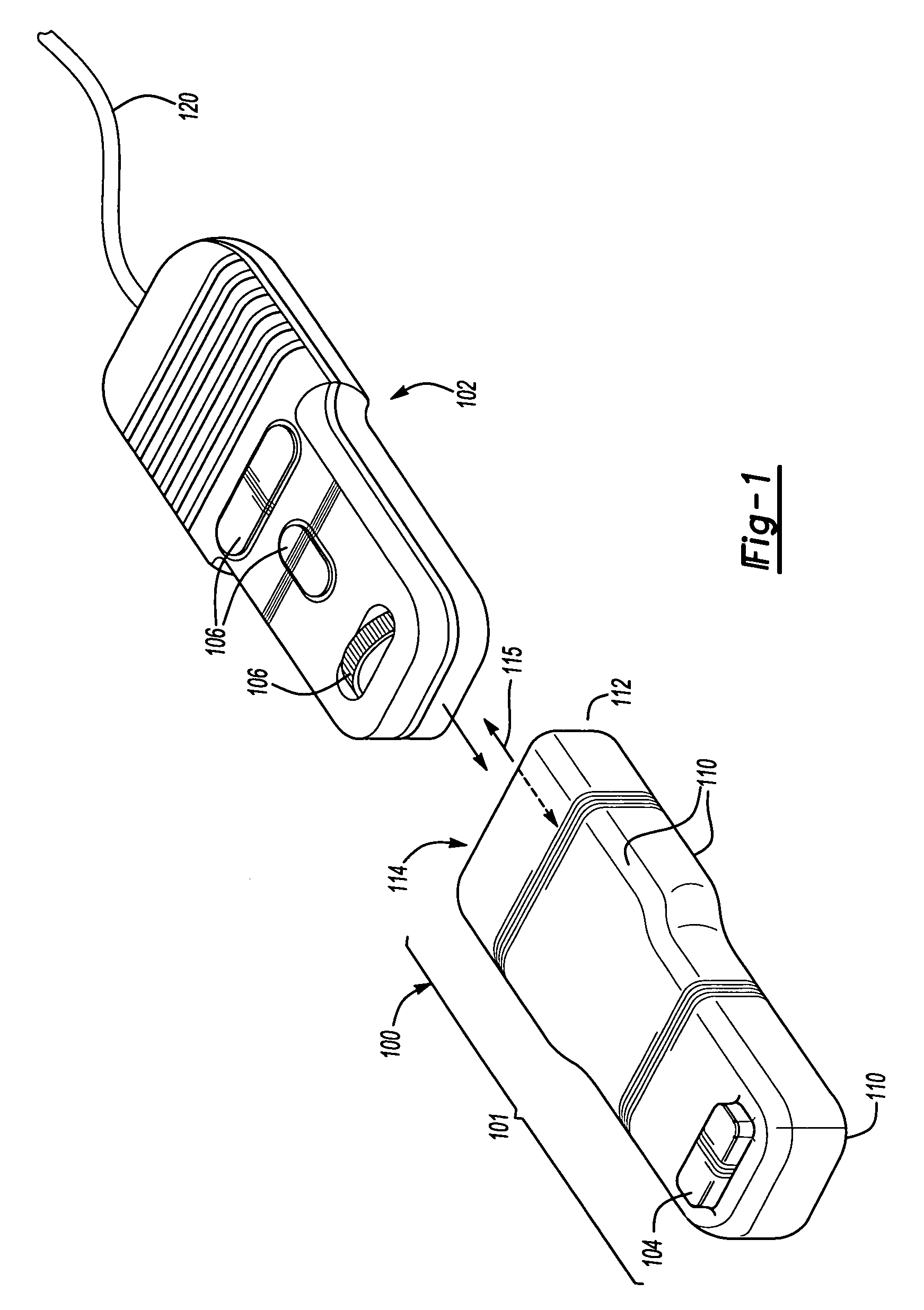
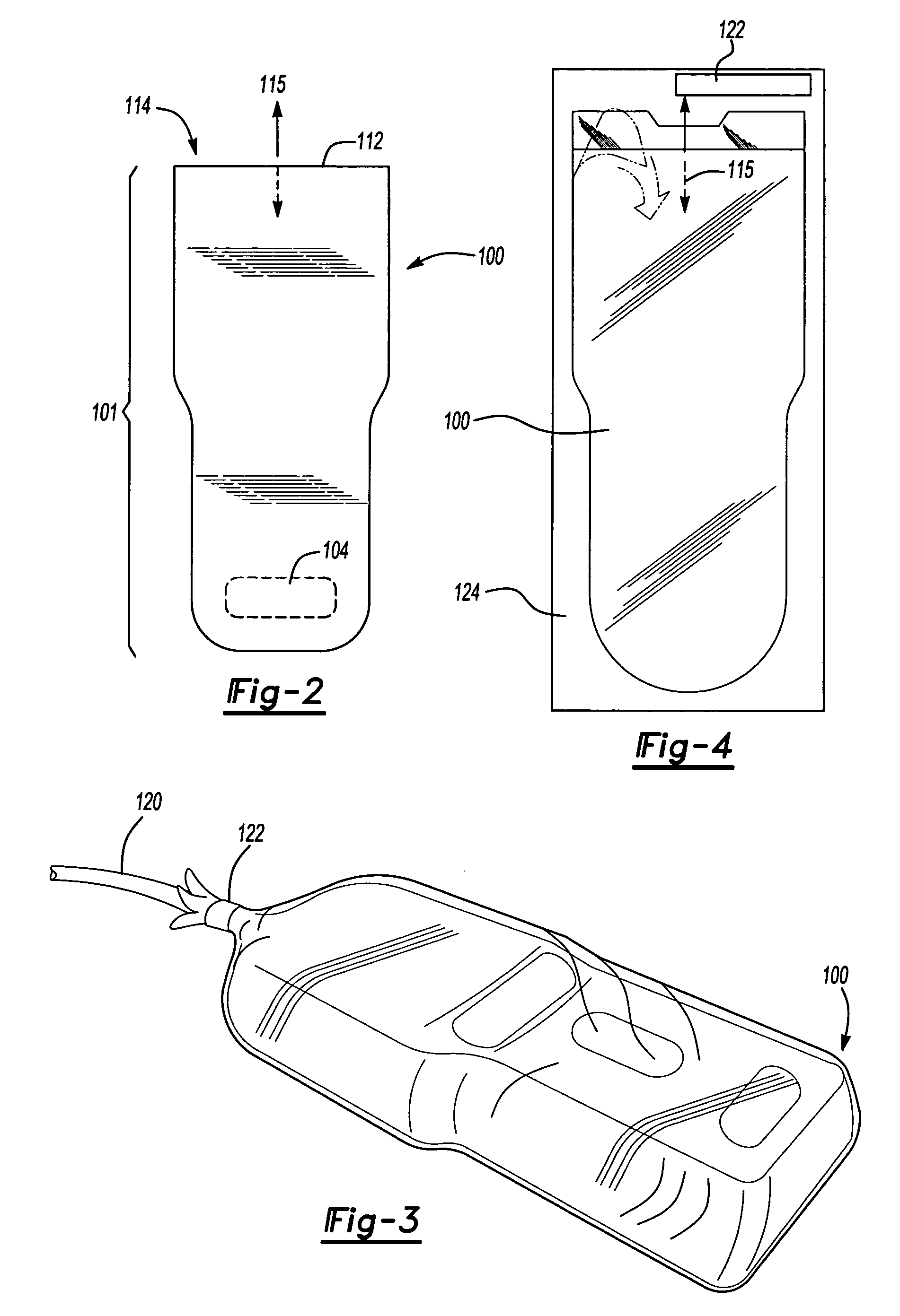
[0012]FIGS. 1 through 4 illustrate a shield 100 designed to cover a patient control device (e.g., a nursecall, television control, light control, all-in-one unit, etc) 102. In one embodiment, the shield 100 has a sheath portion 101 with a shape that generally matches the shape of the nursecall device 102 so that the shield 100 will conform to the nursecall device's 102 shape without leaving any undesired gaps between the shield 100 and the unit 102. In one embodiment, the sheath portion 101 has one or more elevations 104 that ultimately are aligned above one or more controls 106 on the nursecall device, such as a lever or a dial.

[0013]The material used to form the shield 100 may be any material that allows the sheath portion 101 to fit snugly around the nursecall device 102 while still being flexible enough to allow controls 106 to be operated through the elevations 104 and through the shield 100 itself. Because the controls 106 are touched frequently and often have crevices, they a...


PUM


Abstract

A disposable shield designed to sheath a patient control device prevents contaminants from contacting or entering the device. The shield has a bi-directional opening through which the hand-operated device is inserted and removed from the shield. A removable sealing device is used to preserve the integrity of the shield when the sealing device is removed. The shield can therefore be changed each time the device is handled by a different person, minimizing the chances of cross-contamination. The shield also extends the life of the device by preventing biological contaminants from contacting the device.

Description

REFERENCE TO RELATED APPLICATIONS[0001]This application is a continuation-in-part of U.S. application Ser. No. 10 / 214,518, filed on Aug. 8, 2002 now abandoned, which claims priority to U.S. Provisional Application No. 60 / 390,619 filed on Jun. 21, 2002.TECHNICAL FIELD[0002]The present invention relates to patient control devices, such as nursecalls, light controls, and television controls, used in medical facilities, and more particularly to a cover for protecting a patient control device.BACKGROUND OF THE INVENTION[0003]Medical facilities, such as hospitals, use patient control devices, such as nursecall devices, to allow patients to alert nurses and control environmental settings such as light levels and television channels. The nursecall device normally includes control circuitry inside a case and is placed in a patient's bed for easy access. Because the nursecall device can be located anywhere in the bed with the patient, the unit can easily become contaminated with various conta...

Claims


Application Information

Patent Timeline
IPC IPC(8): A61B17/06A61B19/08A61G12/00
CPCA61B19/081Y10T428/13A61G2203/12A61G12/00A61B46/10
Inventor CLARK, DAN WARRENPARKER, RUSSELL DEAN
Owner BIOTRONICS
Why Eureka
Try Eureka