Liquid vapor delivery system and method of maintaining a constant level of fluid therein

a technology of liquid vapor and liquid vapor, which is applied in the direction of heating types, separation processes, applications, etc., can solve the problems of reducing the maximum allowable volume of many of these fluids, significant variations in the liquid level have a pronounced adverse effect, and fail to eliminate the need for some degree of level control. , to achieve the effect of convenient cleaning

Inactive Publication Date: 2006-03-14
MATHESON TRI GAS INC
View PDF18 Cites 33 Cited by
  • Summary
  • Abstract
  • Description
  • Claims
  • Application Information

AI Technical Summary

Benefits of technology

[0017]In another form of the invention, the bubbler floor is adapted to drain all liquid or reagents out of the bubbler through the liquid source line thus allowing for ease in cleaning.

Problems solved by technology

This has resulted in reducing the maximum allowable volumes of many of these fluids within the work place.
In other applications, however, such as in vapor deposition procedures employed in constructing semiconductors and optical fiber preforms, significant variations in the level of liquid have a pronounced adverse effect.
While theoretically possible to program a heat controller to account for these variables as changes in the level of liquid are continuously monitored, that approach is complex and fails to eliminate the need for some degree of level control to prevent complete depletion or flooding.
Vaporization rate also defines the headspace present above and within the bubbler container, which has been found to negatively effect the vapor concentration and ultimate bubbler performance when not optimized.
Such methods can result in reducing many of the concerns associated with prior art expendable bubblers, such as reducing the risk of contamination during ampoule replacement or any necessary fluid replenishment, but create a host of potential problems including metal fatigue, sealing of dissimilar materials, and need for calibration procedures.
Such devices are prone to failure, or inaccuracies and are generally the most common failure mechanism in the system.
However, the use of such devices can be costly, prone to error, and with many of the fluids being flammable, represent ignition sources if not properly rated and maintained.
The corrosive and toxic nature of the materials commonly encountered greatly limit the materials and construction of sensors used in these demanding applications.
Although the system works well, perturbations in the deposition bubbler caused by a drop in liquid level and then a rise due to the changing of the pressure in the reservoir can to an extent affect adversely the rate of vaporization and hence the concentration level of the vapor.
However, while this system is effective, the slow rate at which the overall temperature of the liquid can be changed, particularly cooled, often results in an unwanted delay in achieving the desired concentration level corrections.

Method used


Image

  • Liquid vapor delivery system and method of maintaining a constant level of fluid therein
  • Liquid vapor delivery system and method of maintaining a constant level of fluid therein
  • Liquid vapor delivery system and method of maintaining a constant level of fluid therein

Examples


Embodiment Construction

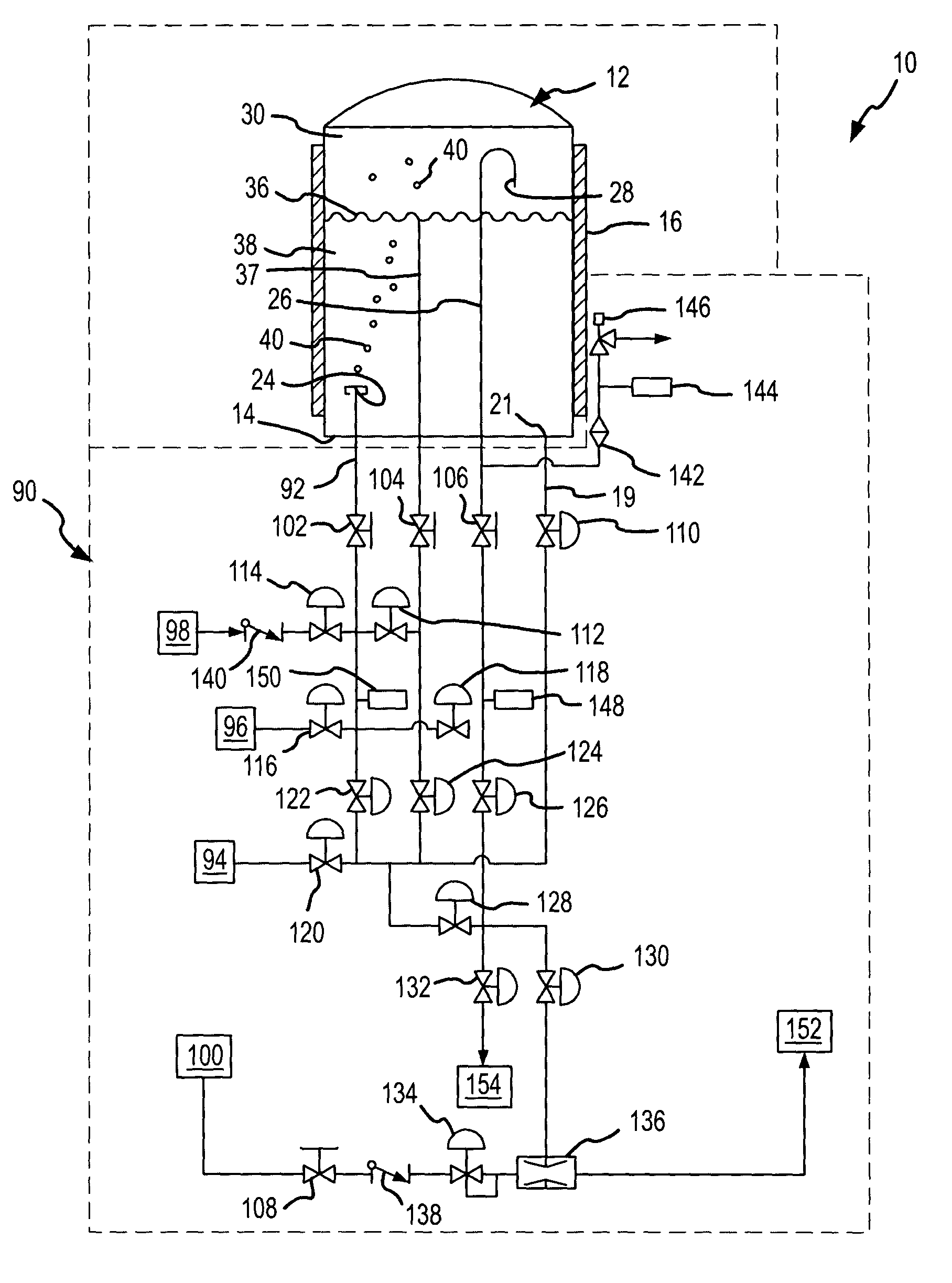
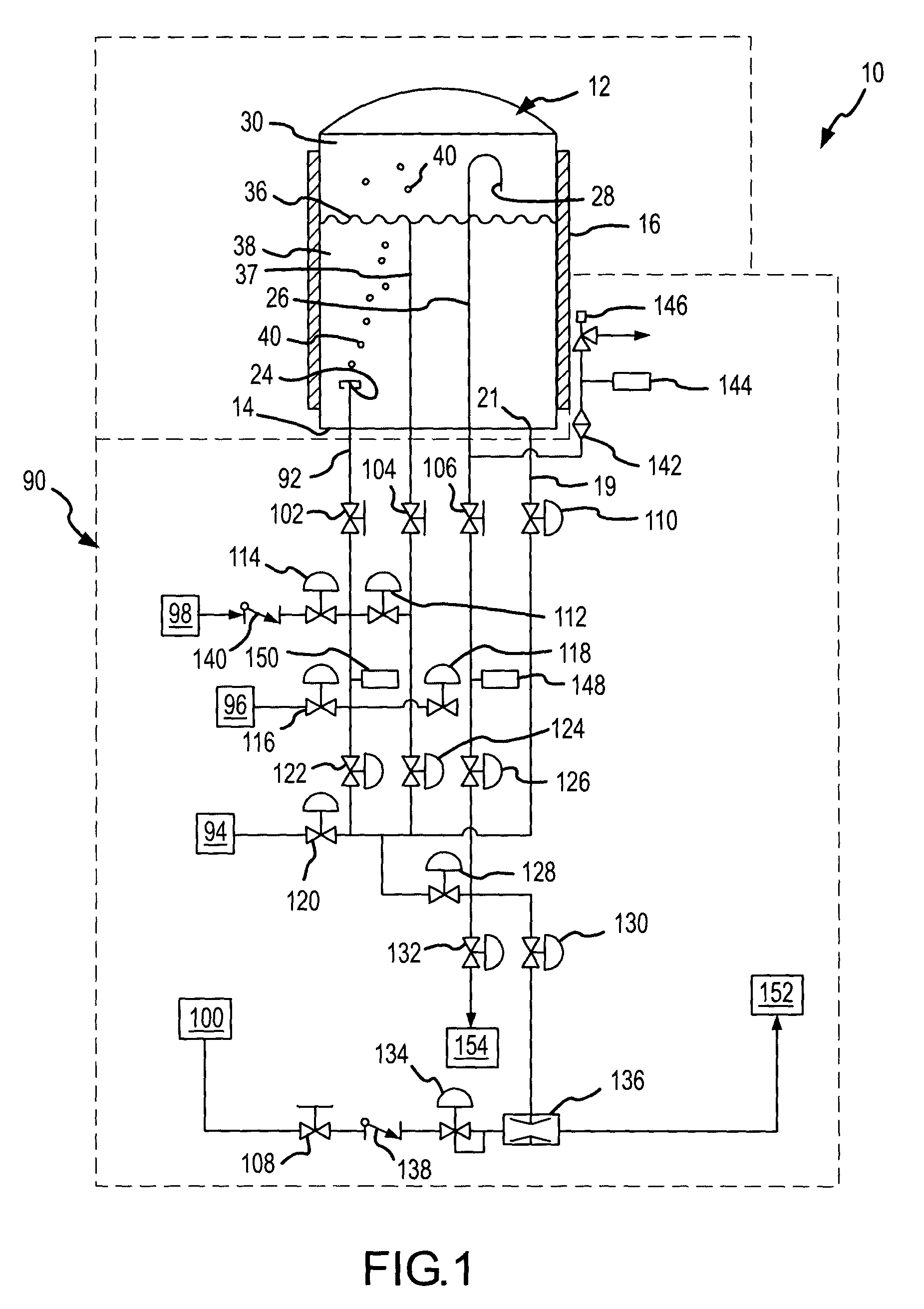
[0023]The liquid vapor delivery system 10 according to the present invention is best seen in FIG. 1. The liquid vapor delivery system 10 is designed to provide a vapor stream of an easily vaporizable liquid or reagent 38 which is contained in a reservoir 94 and in a bubbler 12. In general, the present invention involves adjusting the pressure within the headspace of bubbler 12 to that of the chemical fluid level line 37, thus creating a repeatable fluid level based on pressure and fluid dynamics and not relying on conventional level sensors and controllers. This is accomplished in two stages. During the first stage, all inlets and outlets of the bubbler 12 are set in a closed position except valves 102, 104 and 106. To begin the refill cycle, valves 120 and 110 are then opened to initiate the flow of liquid 38 from liquid source 94 to the bubbler 12. The system, during the refill cycle, allows over-filling of the liquid level 38 in bubbler 12 to a level controlled by the pressure of...


PUM

PropertyMeasurementUnit
heightaaaaaaaaaa
pressureaaaaaaaaaa
concentrationaaaaaaaaaa

Abstract

In accordance with the present invention, a method and system is described for controlling the delivery of vapor from a bubbler containing a supply of chemical fluid through which a carrier gas is bubbled and from which bubbler vapors are delivered in a vapor stream entrained with the carrier gas. In general, the present invention involves equilibrating the pressure within the head space to that of the chemical fluid fill line, thus maintaining a constant fluid level based on pressure and not relying on conventional level sensors and controllers.

Description

CROSS REFERENCE TO OTHER APPLICATIONS[0001]This application claims the benefit of U.S. provisional application No. 60 / 411,026 filed Sep. 16, 2002 which is incorporated herein by reference.BACKGROUND OF THE INVENTION[0002]1. Field of the Invention[0003]This invention relates to liquid vapor delivery systems of the type employing bubblers and to methods of maintaining constant levels of reagent within bubblers.[0004]2. Description of the State of Art[0005]The semiconductor industry is very dependent upon sources of ultrahigh purity reagents. Other industries also have high purity requirements, but few compare with the purity requirements in the semiconductor industry. Liquid vapor delivery systems are used in a number of manufacturing processes. For example, liquid vapor delivery systems are used in the manufacture of optical wave-guides. Such systems are described in U.S. Pat. Nos. 3,826,560; 4,235,829; and 4,276,243, the disclosures of which are incorporated herein by reference. Thi...

Claims


Application Information

Patent Timeline
Patent Type & Authority Patents(United States)
IPC IPC(8): B01F3/04C23C16/448
CPCC23C16/4482Y10S261/65
Inventor CURRAN, WILLIAM J.
Owner MATHESON TRI GAS INC
Why Eureka
Try Eureka