Bioprosthetic cardiovascular valve system

a bioprosthetic and valve system technology, applied in the field of artificial heart valves, can solve the problems of affecting the survival rate of patients, and affecting the safety of patients, and achieving the effects of reducing the risk of vascular diseas

Inactive Publication Date: 2006-03-14
THE CLEVELAND CLINIC FOUND
View PDF35 Cites 588 Cited by
  • Summary
  • Abstract
  • Description
  • Claims
  • Application Information

AI Technical Summary

Benefits of technology

[0031]Another advantage of the present invention is the provision of an expandable, re-collapsible tissue-based cardiovascular valve.
[0032]Another advantage of the present invention is the provision of an expandable, re-collapsible valve that is small enough to be delivered by catheters by way of a percutaneous puncture.
[0033]Another advantage of the present invention is the replacement of a re-collapsible valve by way of conventional or minimally invasive cardiac surgery.
[0034]Still another advantage of the present invention is the provision of a catheter-based valve delivery system.
[0035]Still another advantage of the present invention is the provision of a valve delivery system consisting of surgical tools that can remove and deliver a re-collapsible valve by way of small incisions in the blood vessels that emerge from the heart, or in the wall of the heart itself.
[0036]Still another advantage of the present invention is the provision of a stable surgical platform within which catheter-based manipulators can be securely anchored so that intracardiac procedures can be properly executed.

Problems solved by technology

This process can take several hours and subjects the patient to significant operative mortality.
While the mortality during first valve replacement surgery can be very low (less than 5%), the second surgery carries much greater operative mortality, and the third is even more risky (>15%).
Anticoagulant themselves, however, carry a measurable risk of bleeding and thromboembolism and are not an ideal solution.
This has thus far been an extremely difficult goal to reach.
Deployment of stents and other permanent devices has become commonplace, but to date, no successful, catheter deployable valve has been developed.
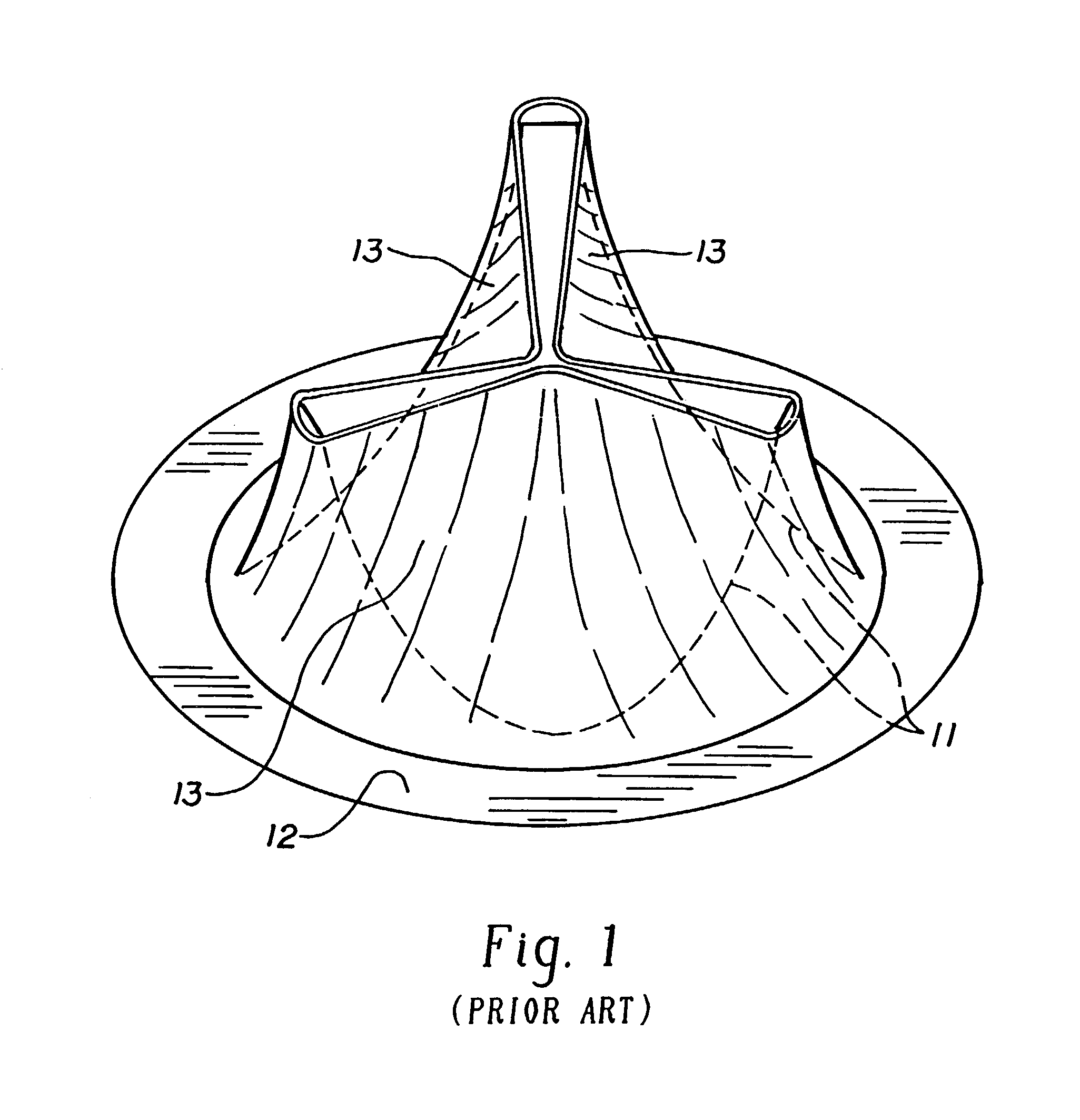
While U.S. Pat. No. 5,545,214 discloses a balloon-deployable tissue valve, the technology is similar to that of stents, and is not ideal for tissue heart valves.
Good durability, however, is not easily attained.
The manufacturing process of tissue heart valves is very mature and complex from the quality control point of view, and only minimal improvements in valve durability have been achieved in recent years.
Major improvements in valve durability are therefore not expected in the near future.

Method used


Image

  • Bioprosthetic cardiovascular valve system
  • Bioprosthetic cardiovascular valve system
  • Bioprosthetic cardiovascular valve system

Examples


Embodiment Construction

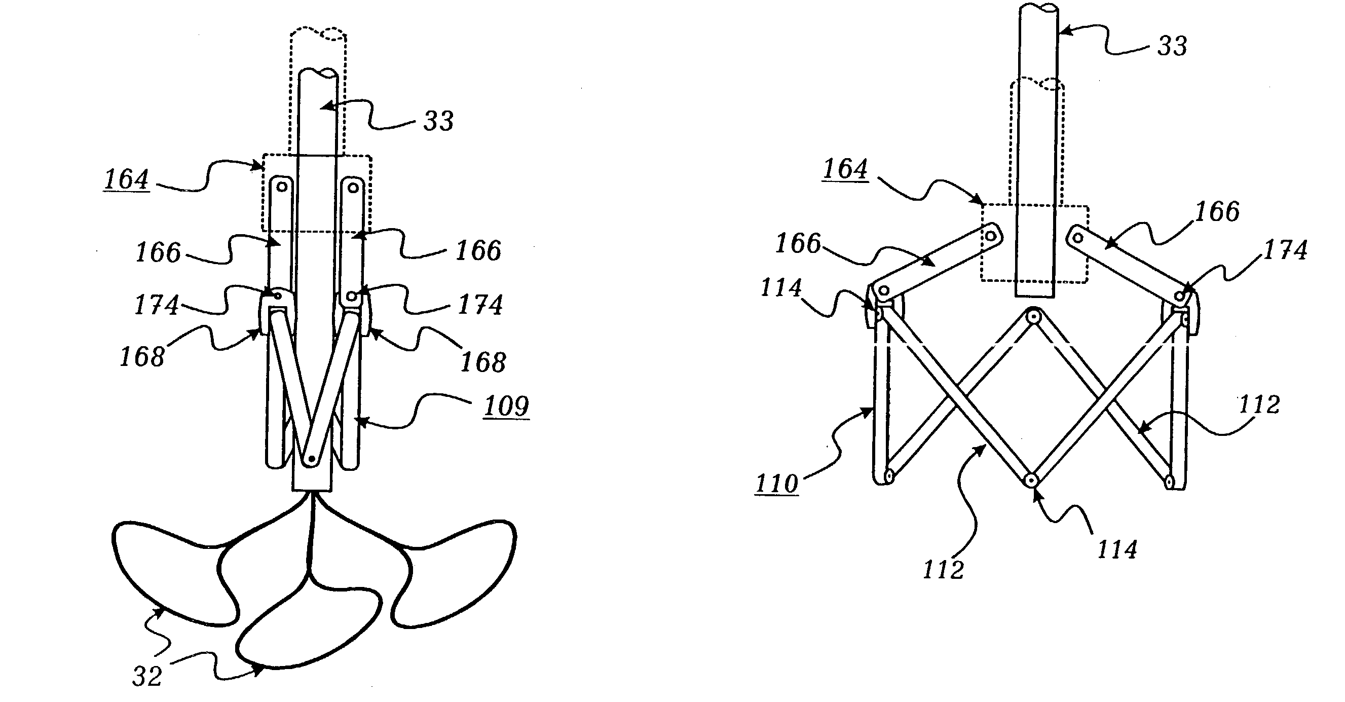
[0093]The detailed description set forth below in connection with the appended drawings is intended merely as a description of the presently preferred embodiments of the invention, and is not intended to represent or limit the form in which the present invention can be constructed or used. The description sets forth the function and sequence of steps for construction and implementation of the invention. It is to be understood that the same or equivalent functions and sequences may be accomplished by different embodiments that are also intended to be encompassed within the spirit and scope of the invention. For example, a similar valve system can be used to insert a similar collapsible valve (e.g., a prosthetic valve or endoprosthesis) into the mitral position, the pulmonary and tricuspid positions of the heart or another expandable prosthetic device into any other location within the vasculature or an organ of any patient. Moreover, while a preferred embodiment of the present invent...


PUM


Abstract

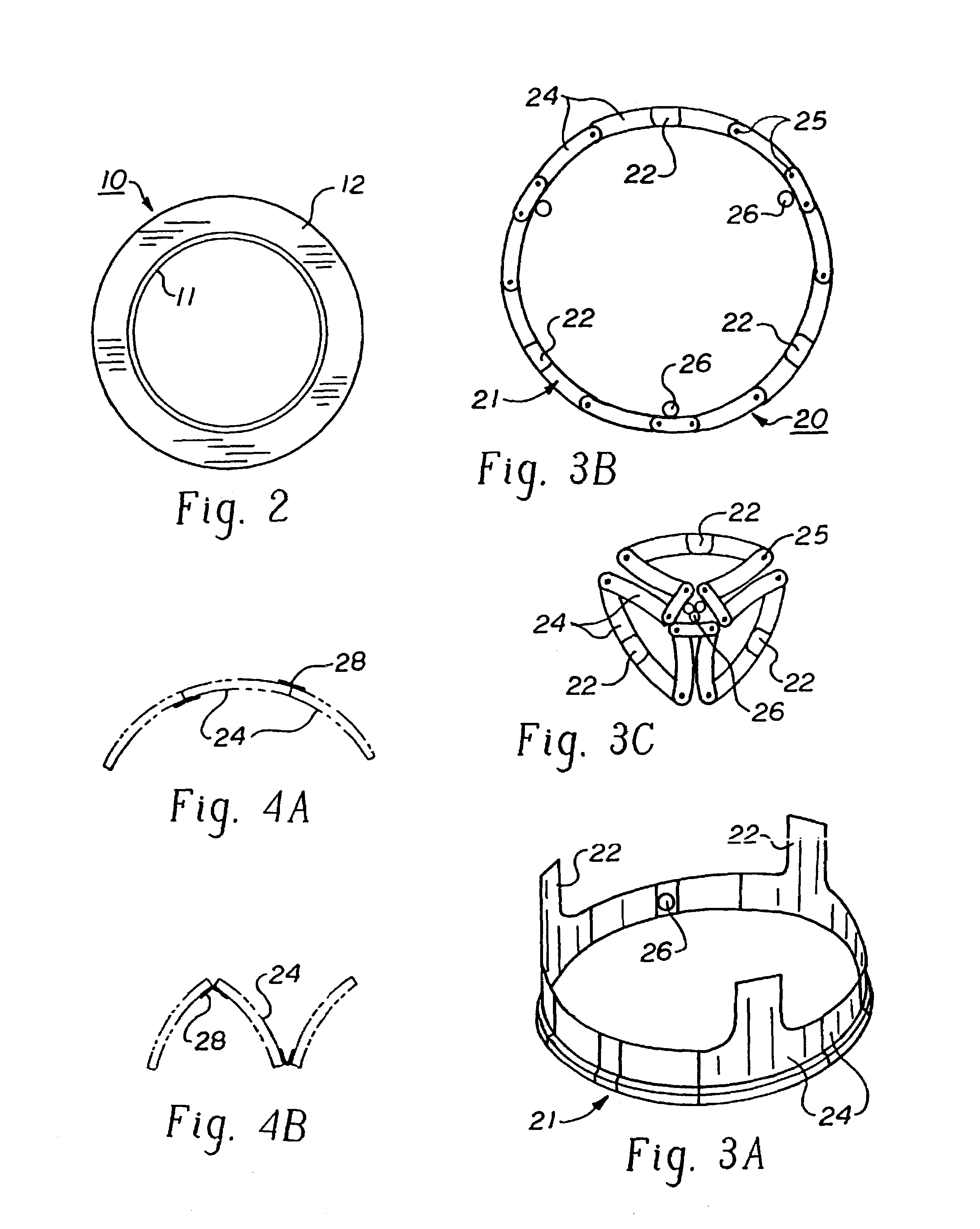
A cardiovascular valve system including a permanent base unit that is affixed to the patient using conventional sutures or staples, and a collapsible valve having a collapsible frame that mates with the permanent base unit, and supports valve leaflets. An installed collapsible frame may be re-collapsed and disengaged from the permanent housing. A new collapsible valve is then installed, to resume the function of the prosthesis.

Description

RELATED APPLICATIONS[0001]This is a continuation of U.S. application Ser. No. 09 / 745,240 filed Dec. 21, 2000 now U.S. Pat. No. 6,530,952, which is a continuation-in-part of U.S. application Ser. No. 09 / 597,918 filed Jun. 19, 2000 now U.S. Pat. No. 6,569,196, which is a continuation of International Application PCT / US98 / 27481, with an international filing date of Dec. 23, 1998, which claims the benefit of U.S. Provisional Application No. 60 / 068,711 filed Dec. 29, 1997.BACKGROUND OF THE INVENTION[0002]The current practice of inserting artificial heart valves involves cutting the chest open, placing the patient on cardiopulmonary bypass, and surgically inserting the valve into an aorta. This process can take several hours and subjects the patient to significant operative mortality. While the mortality during first valve replacement surgery can be very low (less than 5%), the second surgery carries much greater operative mortality, and the third is even more risky (>15%). Consequentl...

Claims


Application Information

Patent Timeline
Patent Type & Authority Patents(United States)
IPC IPC(8): A61F2/24A61F2/06A61B17/28A61B19/00
CPCA61F2/2409A61F2/2418A61F2/2427A61F2/243A61F2/2439A61F2/2412A61B2017/2944A61B2019/5429A61B2019/547A61F2220/0066A61B2090/3929A61B2090/397
Inventor VESELY, IVAN
Owner THE CLEVELAND CLINIC FOUND
Why Eureka
Try Eureka