Inspection method and inspection apparatus for detecting defects

a technology of inspection apparatus and test object, which is applied in the direction of optical radiation measurement, separation process, instruments, etc., can solve the problems of preventing the performance expected of the material from being fully displayed, interfering with the filtering performance of the porous member or the performance, and difficult inspection, so as to facilitate post-treatment inspection and identification. , the effect of easy recording

Inactive Publication Date: 2006-03-14
NGK INSULATORS LTD
View PDF9 Cites 36 Cited by
  • Summary
  • Abstract
  • Description
  • Claims
  • Application Information

AI Technical Summary

Benefits of technology

[0013]In the inspection method according to the present invention, to easily identify the location of a defect, it is preferable that the light is planarly emitted to detect a defect in a two-dimensional fashion. Furthermore, to easily record the location of detection, it is preferable that an image of the visualized and detected particulate is recorded by a camera. In addition, from the viewpoint of detection sensitivity and easier post-treatment, a particle diameter of the particulate generated is preferably 0.3 to 200 μm, and more preferably 0.5 to 50 μm, and still more preferably 1 to 10 μm. The inspection method for detecting a defect in accordance with the present invention can be preferably used when a test object is a porous member, and also preferably used when the test object is a honeycomb structure, especially a diesel particulate filter. In this case, from the aspect of detection sensitivity, the light is emitted such that it passes in the vicinity of a surface from which the particulate discharged and substantially in parallel to the surface from which the particulate is discharged.
[0015]To allow the location of detection to be easily identified, the light emitting means of the inspection apparatus for detecting a defect in accordance with the present invention is preferably a means for planarly emitting the light. Furthermore, to allow the location of a defect to be easily recorded, the inspection apparatus for detecting a defect in accordance with the present invention preferably further comprises a recording means for recording an image of the particulate that has been visualized and detected. In addition, from the viewpoint of detection sensitivity and easier post-treatment, the particulate generating means of the apparatus for detecting a defect in accordance with the present invention is preferably a means for generating particulates having particle diameters of 0.3 to 200 μm, more preferably 0.5 to 50 μm, and still more preferably 1 to 10 μm. The inspection apparatus for detecting a defect in accordance with the present invention is used for preferably a porous member, more preferably a honeycomb structure, and particularly a diesel particulate filter as a test object. In this case, from the aspect of detection sensitivity, the inspection apparatus for detecting a defect in accordance with the present invention preferably comprises the light emitting means for emitting light such that it passes substantially in parallel to a particulate discharge surface of the honeycomb structure from which the particulate is discharged.

Problems solved by technology

Therefore, the presence of a hole, i.e., a defect, that pierces the film or wall of a porous member interferes with the filtering performance of the porous member or the performance as a catalyst carrier.
In the case of a nonporous member, a hole, that is, a defect, frequently prevents the performance expected of the material from being fully exhibited.
There are, however, some cases where the inspection is difficult, depending on the configuration, or the position or the size of a defect to be detected, of a test object, which may be a porous member or a nonporous member.
Hence, defects in the partitions of such a structure cannot be observed from outside.
However, since the method involves the use of a soot-like substance, the soot-like substance that adheres to a honeycomb structure must be removed by heat treatment after inspection, and a few hours are required for such post-treatment.
In addition, inspecting one test object requires 5 to 6 minutes.
The post-treatment of this method does not take as long as that of the aforesaid soot print method; however, the honeycomb structure has to be dried after the inspection, and also has to be de-foamed in water prior to the inspection, which takes time.

Method used


Image

  • Inspection method and inspection apparatus for detecting defects
  • Inspection method and inspection apparatus for detecting defects
  • Inspection method and inspection apparatus for detecting defects

Examples


example 1

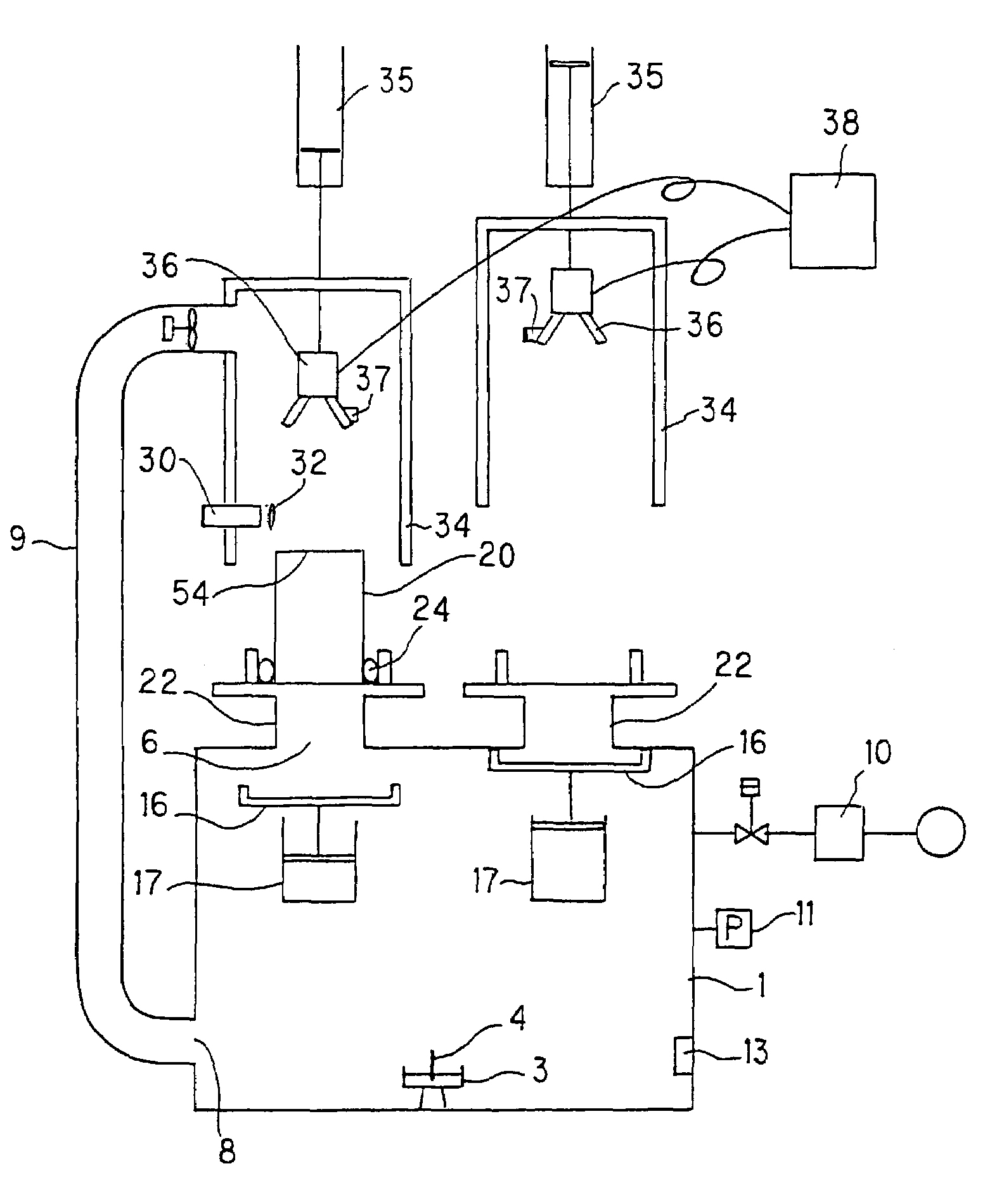
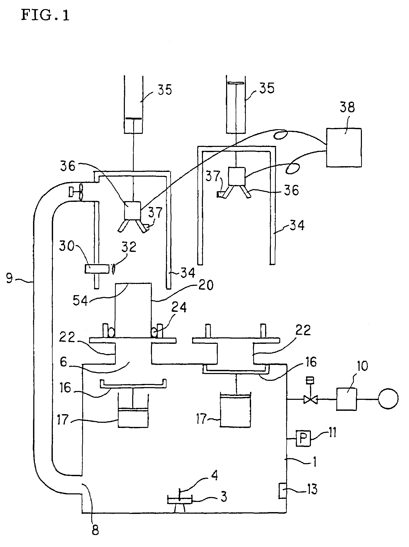
[0044]Using the seal 24, the filter (a) was set on the mounting base 22 of the apparatus for checking a test object for defects shown in FIG. 1. Then, an incense stick was burnt to generate particulates of the particle size distribution shown in FIG. 5. When the concentration of the particulates reached 300 cells / cc, the inside of the particulate chamber was pressurized at 10 Pa by the pressurizing mechanism 10 to introduce the particulates into the filter (a). A He—Ne laser beam emitter was used as the light emitter 30, and a laser beam was emitted through the lens 32, the laser beam being planarly passed substantially in parallel to the upper surface of the filter (a) (the particulate discharge surface 54) at 3 mm above the filter (a). The laser beam irregularly reflected by discharged particulates was photographed by the CCD camera 36 and observed and recorded by the monitor 38. The time required from the start of the inspection to the photographing was five seconds. The filterin...

examples 2 and 3

[0045]The inspections were carried out for the filters (b) and (c) in the same manner as that of Example 1. The time required from the start of the inspection to photographing was five seconds. The filtering functions remained intact even when post-treatment was not carried out after the inspection. The photographed images are shown in FIG. 6(b) and FIG. 6(c).


PUM

PropertyMeasurementUnit
pressureaaaaaaaaaa
particle diameteraaaaaaaaaa
particle diametersaaaaaaaaaa

Abstract

An inspection method for detecting a defect in a test object. A particulate is generated, then the generated particulate is introduced into a test object. Subsequently, light having high directivity is emitted such that the light passes in the vicinity of the test object to irradiate the particulate discharged from the test object, thereby making the particulate visible. An inspection apparatus for detecting a defect in a test object, including a particulate generator, a particulate introducing device which introduces the particulate into a test object, and a high directional light emitter emitting light passing in the vicinity of the test object and irradiating the particulate discharged from the test object to visualize the particulate. The inspection method and apparatus can detect a defect with high sensitivity and shorten an inspection time and a post-treatment time.

Description

TECHNICAL FIELD[0001]The present invention relates to an inspection method and an inspection apparatus for detecting a defect of a test object and, more particularly, to an inspection method and an inspection apparatus for detecting a defect of a test object that allow a defect to be detected with high sensitivity and permit quick inspection and post-processing.BACKGROUND ART[0002]Test objects requiring inspection for detecting defects include, for example, porous members. Porous members are extensively used for filters or catalyst carriers, etc. Porous members are used, for instance, for the exhaust gas purifiers of heat engines, such as internal combustion engines, or combustion equipment, such as boilers, for reformers of liquid fuel or gas fuel, and for purifying facilities of water supply and sewerage. Furthermore, honeycomb-shaped porous members are used for diesel particulate filters or hot gas dust collectors to capture and remove particulate substances contained in a dust c...

Claims


Application Information

Patent Timeline
Patent Type & Authority Patents(United States)
IPC IPC(8): G01N21/00G01N15/08B01D46/00B01D46/44B01D65/10F01N3/00F01N3/02G01M3/20G01M3/38G01N21/88G01N21/95
CPCB01D46/0086B01D46/442B01D65/102B01D65/104G01N21/95692G01M3/38G01N15/0826G01N21/88G01N21/95G01M3/20B01D2273/18
Inventor ENOMOTO, AKIOMIYASHITA, KOUICHI
Owner NGK INSULATORS LTD
Why Eureka
Try Eureka