
Optical imaging system with rod lens array

an optical imaging system and lens array technology, applied in optics, instruments, projectors, etc., can solve the problems of change in resolving power and resolving power, and achieve the effects of reducing cost, simplifying distance adjustment, and increasing periodic irregularity in image plane brightness

Active Publication Date: 2006-03-14
NIPPON SHEET GLASS CO LTD
View PDF4 Cites 1 Cited by
  • Summary
  • Abstract
  • Description
  • Claims
  • Application Information

AI Technical Summary

Benefits of technology

[0016]This preferred example can provide an optical imaging system having a more favorable refractive index distribution.
[0020]In the optical imaging system according to the configuration of the present invention, it is preferable that the radius r0 of the portion of each rod lens functioning as a lens is in the range of 0.05 mm≦r0≦0.60 mm. This preferred example can facilitate production and assembly of the rod lenses and suppress the aberrations of the rod lens array significantly.
[0024]In the optical imaging system according to the configuration of the present invention, it is preferable that a parallel plane transparent substrate is arranged so that the manuscript plane is located at the front focal position of the rod lens array. This preferred example allows the manuscript plane to be set at the front focal position by only pressing a manuscript to the surface of the transparent substrate. Moreover, it is preferable that the parallel plane transparent substrate is in contact with the lens surface of the rod lens array. This can be achieved easily by adjusting the thickness of the transparent substrate. This preferred example can simplify adjustment of the distance between the rod lens array and the front focal position during fabrication of the optical imaging system, thereby reducing the cost.

Problems solved by technology

However, in the case of a plurality of rod lenses arranged in an array, a change in the resolving power may be caused not only by the spherical aberration, field curvature and astigmatism of the individual lenses but also by the overlapping of images from neighboring lenses.
Even if the rod lenses have the same refractive index distribution, the overlapping degree m changes with the lens length, and thus causing a change in the resolving power.

Method used


Image

  • Optical imaging system with rod lens array
  • Optical imaging system with rod lens array
  • Optical imaging system with rod lens array

Examples


Embodiment Construction

[0047]Hereinafter, the present invention will be described more specifically by way of an embodiment.

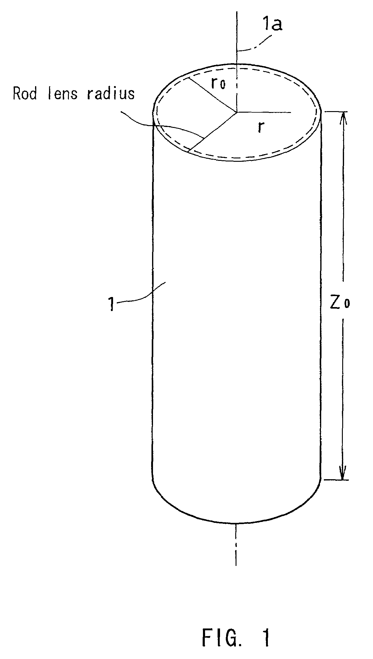
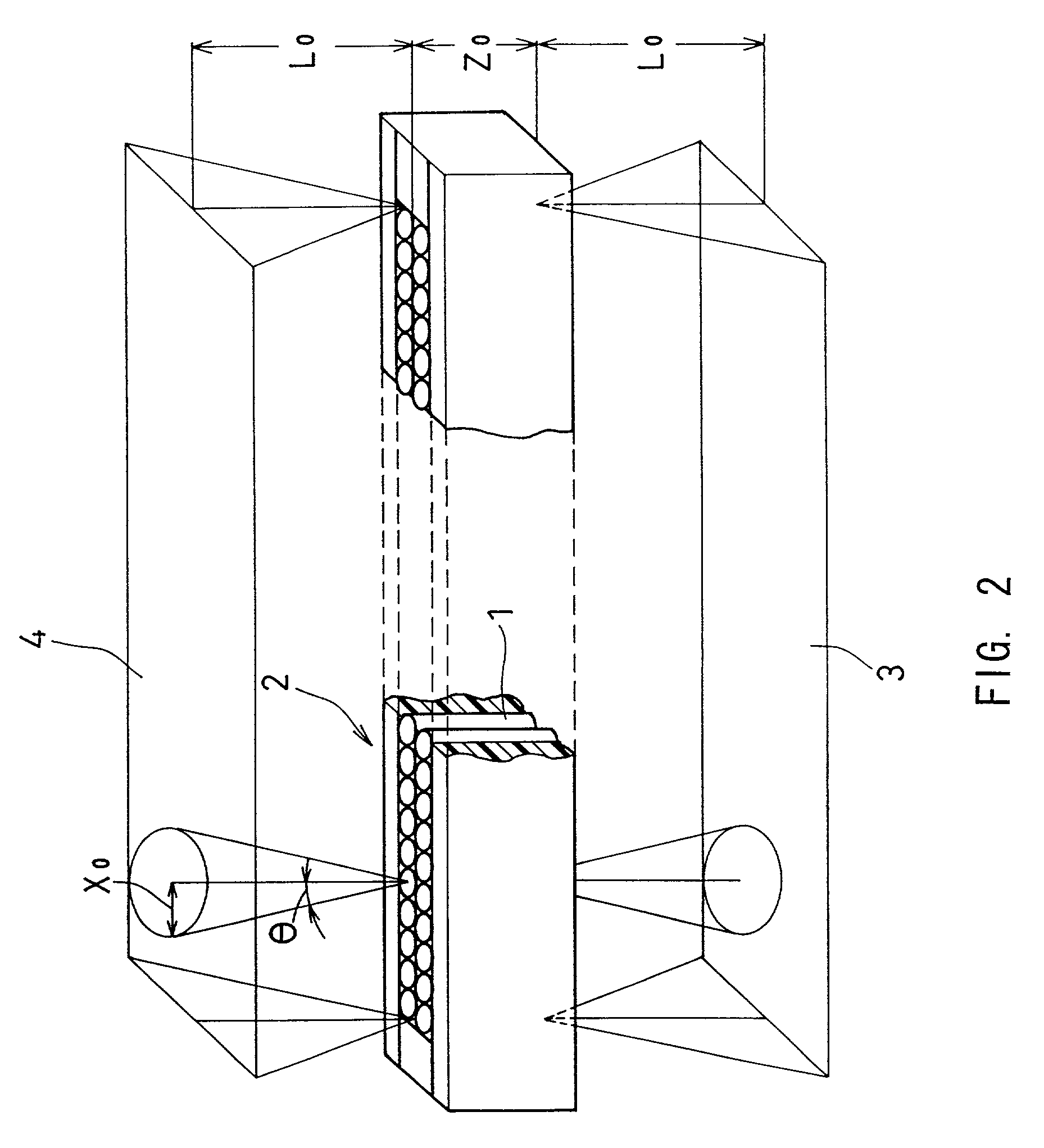
[0048]As shown in FIGS. 1 and 2, this embodiment employs a rod lens array 2 for one-to-one imaging, where a plurality of columnar rod lenses 1 having a refractive index distribution in the radial direction are arranged in two rows with their optical axes 1a in parallel. A manuscript plane 3 and an image plane 4 are located on the opposite sides of the rod lens array 2, thus providing an optical imaging system.

[0049]As shown in FIG. 3, the refractive index n of the rod lenses 1 is distributed in the radial direction, which is expressed by

n(r)2=n02·{1−(g·r)2+h4·(g·r)4+h6·(g·r)6+h8·(g·r)8}  Eq. 13

where r is a radial distance from the optical axis 1a of the rod lens 1, n(r) is the refractive index at the radial distance r, n0 is the refractive index on the optical axis 1a of the rod lens 1 (i.e., the center refractive index), and g, h4, h6 and h8 are refractive index distribution coeffic...


PUM


Abstract

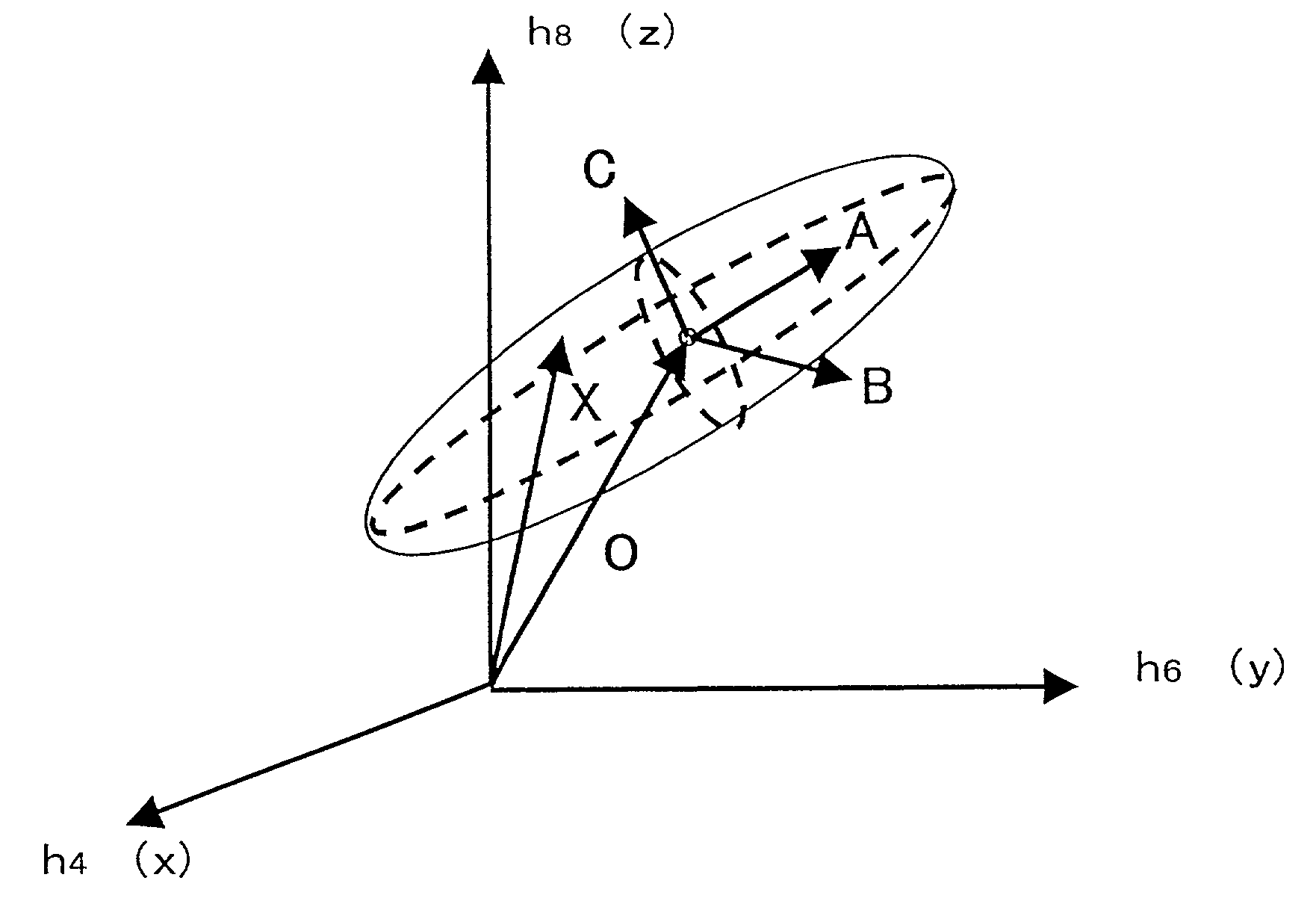
An optical imaging system is provided that includes a rod lens array and has the optimum refractive index distribution for achieving a high resolving power. The refractive index distribution of rod lenses can be expressed byn(r)2=n02·{1−(g·r)2+h4·(g·r)4+h619 (g·r)6+h8·(g·r)8}Eq. 45where r is a radial distance from the optical axis of the rod lenses, n0 is a refractive index on the optical axis of the rod lenses, and g, h4, h6 and h8 are refractive index distribution coefficients. The refractive index distribution coefficients h4, h6 and h8 are set on a spheroid in a Cartesian coordinate system with h4 being x-axis, h6 being y-axis and h8 being z-axis. The spheroid is defined by a vector X* that is expressed byX*=(x, y, z)=O*+kAA*+kBB*+kCC*Eq. 46where O* is a vector from the origin of the Cartesian coordinate system to the center of the spheroid, A*, B* and C* are vectors in the directions of the major axis, the mean axis and the minor axis of the spheroid, respectively, and kA, kB and kC satisfy kA2+kB2+kC2≦1.

Description

BACKGROUND OF THE INVENTION[0001]1. Field of the Invention[0002]The present invention relates to an optical imaging system used in an image transmission portion of, e.g., a facsimile device or a copier. More particularly, the present invention relates to an optical imaging system including a plurality of rod lenses arranged in an array.[0003]2. Description of the Related Art[0004]Optical imaging systems including a plurality of rod lenses with a refractive index distribution in the radial direction that are arranged in an array are widely used in the image transmission portion of, e.g., facsimile devices or copiers.[0005]The refractive index distribution of such rod lenses can be expressed, e.g., byn(r)2=n02·{1−(g·r)2+h4·(g·r)4+h6·(g·r)6+h8·(g·r)8}  Eq. 6where r is a radial distance from the optical axis of the rod lens, n(r) is a refractive index at the radial distance r, n0 is a refractive index on the optical axis of the rod lens (i.e., the center refractive index), and g, h4, h6...

Claims


Application Information

Patent Timeline
IPC IPC(8): G02B3/00G02B13/00H04N1/028H04N1/04
CPCG02B3/0087G02B3/0056
Inventor TOYAMA, MINORUKITTAKA, SHIGEO
Owner NIPPON SHEET GLASS CO LTD
Learn More