Method and apparatus for separating channel signals

Active Publication Date: 2006-03-14
ALLIAN FIBER OPTIC PROD INC +1
View PDF4 Cites 21 Cited by
  • Summary
  • Abstract
  • Description
  • Claims
  • Application Information

AI Technical Summary

Benefits of technology

[0022]According to one aspect of the present invention, a new type of collimator is designed to cause an incident light beam to be projected onto a lens at a small incident angle such that a reflected or returning light beam does not collide with the incident light beam in the lens. In other words, there two optical paths in the lens that are narrowly separated, which requires a pointing angle of the collimator be controlled within a tolerable range. The collimator includes a dual-fiber pigtail and an optical lens. Different from the prior art collimators in which two facets of a fiber and a lens are congruent with respect to an optical axis, the corresponding facets of the pigtail and the optical lens are not congruent with respect to an optical axis. In one embodiment, the facet of the pigtail is made slightly slanted while the facet of the lens is made non-slanted with respect to an optical axis such that an error in the pointing angle observed in the prior art collimators is e

Problems solved by technology

However, a careful study of the implementation 100 reveals some problems in practical applications.
One of the problems is the isolation between the two separated signals.
Another one of the problems is the efficiency of the separated signals.
Because of the residual of one signal leaking into another, there is a loss to the signal, which can be significant when two signals are different in intensity.
With an incident angle as large as 45°, it is very difficult to the implementation 100 to achieve a desired separation

Method used


Image

  • Method and apparatus for separating channel signals
  • Method and apparatus for separating channel signals
  • Method and apparatus for separating channel signals

Examples


Embodiment Construction

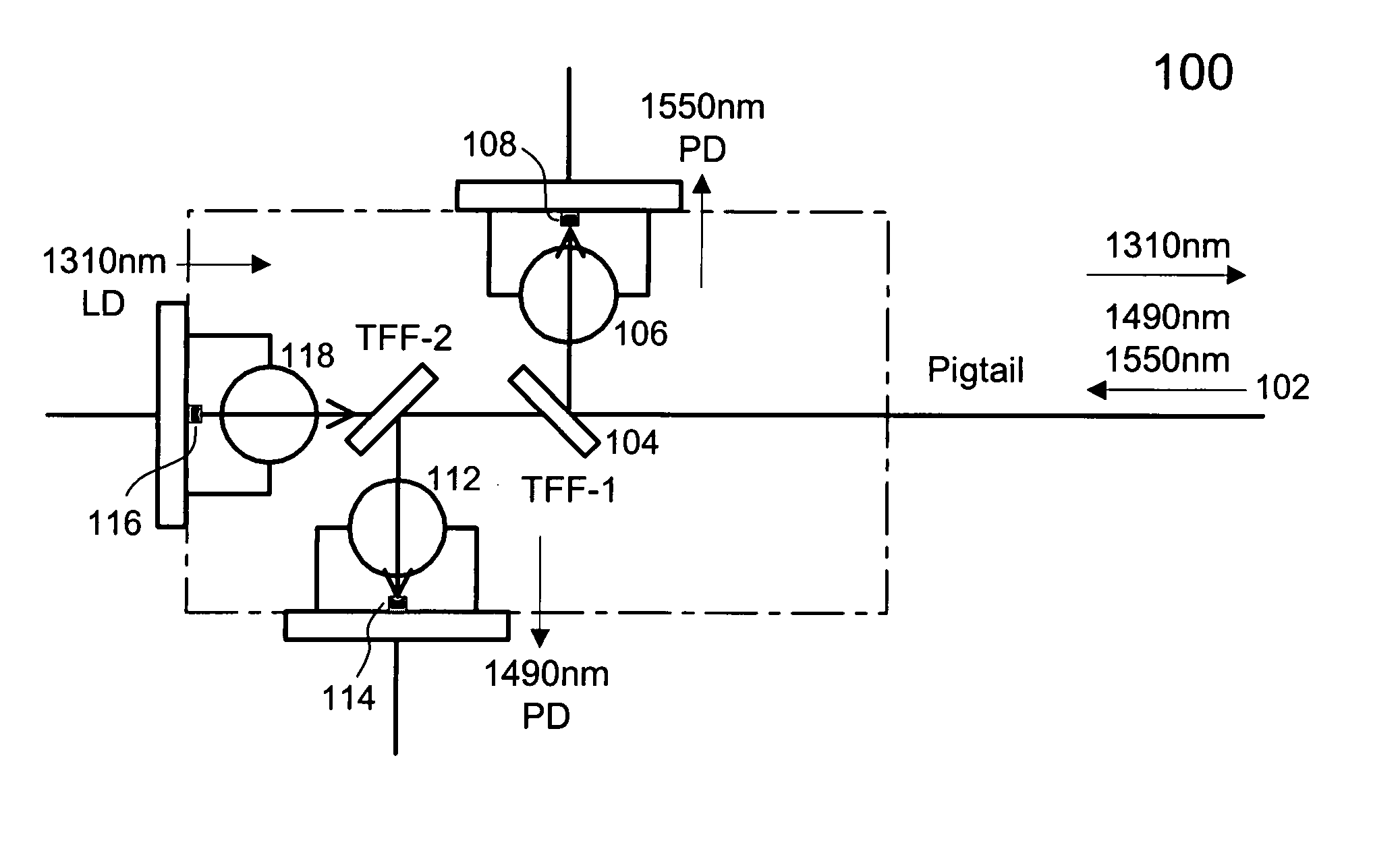
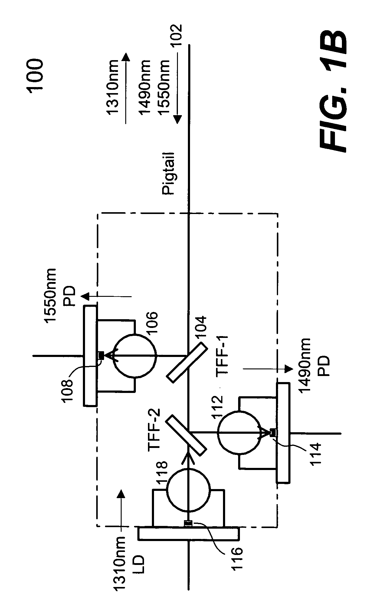
[0037]The present invention pertains to new designs of optical devices particularly useful for separating channels signals that are originally multiplexed. In accordance with the present invention, an optical filter configured to reflect a particular channel signal is positioned to receive a multiplexed signal at a small incident angle so as to minimize residuals of other channel signals in the channel signal. To further increase isolation from the other channel signals, another filter is introduced to transmit only the reflected channel signal, the another filter has a frequency response reciprocal to that of the original optical filter. One of the key advantages, benefits and objects is to increase channel signals separation efficiency by increasing isolation among separated channel signals. The present invention can be advantageously used in communications, particularly in fiber-to-home applications.

[0038]The detailed description of the present invention is presented largely in t...


PUM


Abstract

Designs of optical devices particularly useful for separating channels signals that are originally multiplexed are disclosed. In accordance with one design, an optical filter configured to reflect a particular channel signal is positioned to receive a multiplexed signal at a small incident angle so as to minimize residuals of other signals in the channel signal. To further increase isolation from the other channel signals, another filter is introduced to transmit only the reflected channel signal, the another filter has a frequency response reciprocal to that of the original optical filter. One of the key advantages, benefits and objects of the designs is to increase channel signals separation efficiency by increasing isolation among separated channel signals.

Description

CROSS-REFERENCE TO RELATED APPLICATION[0001]This application is related to U.S. patent application Ser. No. 10 / 600,105, filed Jun. 20, 2003, and entitled “Fiber optic collimators”, which is hereby incorporated by reference.BACKGROUND OF THE INVENTION[0002]1. Field of the Invention[0003]The invention is generally related to the area of optical communications. In particular, the present invention is related to apparatus for separating channel signals with high efficiency and high channel isolation and the method for making the same in compact size.[0004]2. The Background of Related Art[0005]The future communication networks demand ever increasing bandwidths and flexibility to different communication protocols. Fiber optic networks are becoming increasingly popular for data transmission due to their high speed and high capacity capabilities. Wavelength division multiplexing (WDM) is an exemplary technology that puts data from different sources together on an optical fiber with each sig...

Claims


Application Information

Patent Timeline
IPC IPC(8): G02B6/32G02B6/42
CPCG02B6/4246G02B6/29362
Inventor HE, CHUNLI, YAOZHOU, ANDY
Owner ALLIAN FIBER OPTIC PROD INC
Why Eureka
Try Eureka