Modular radiant heat panel system

a radiant heat panel and modular technology, applied in the direction of fluid heaters, heating types, lighting and heating apparatus, etc., can solve the problems of large equipment required to pour concrete slabs, large effort and expense, and complicated installation process

Inactive Publication Date: 2006-03-21
HYDOCK GARY J
View PDF15 Cites 30 Cited by
  • Summary
  • Abstract
  • Description
  • Claims
  • Application Information

AI Technical Summary

Benefits of technology

[0017]Another object of the invention is to provide a radiant heating system which requires less equipment, labor and time to install.
[0021]Another object of the invention is to provide an improved radiant heating system in which the strength characteristics of the thermal mass may be standardized by controlling the conditions under which the thermal mass is poured, formed and cured.
[0028]Another object of the invention is to provide an improved radiant heating system which allows for simplified repair of discreet portions of the system.
[0032]Another object of the invention is to provide an improved radiant heating system in which the thermal mass is composed of a number of easily manipulated panels.
[0039]Another object of the invention is to provide an improved radiant heating system which does not require construction delays to allow for curing of the thermal mass.
[0040]Another object of the invention is to provide an improved radiant heating system which allows for guaranteed batch analysis of the thermal mass.

Problems solved by technology

However, such systems have a number of drawbacks.
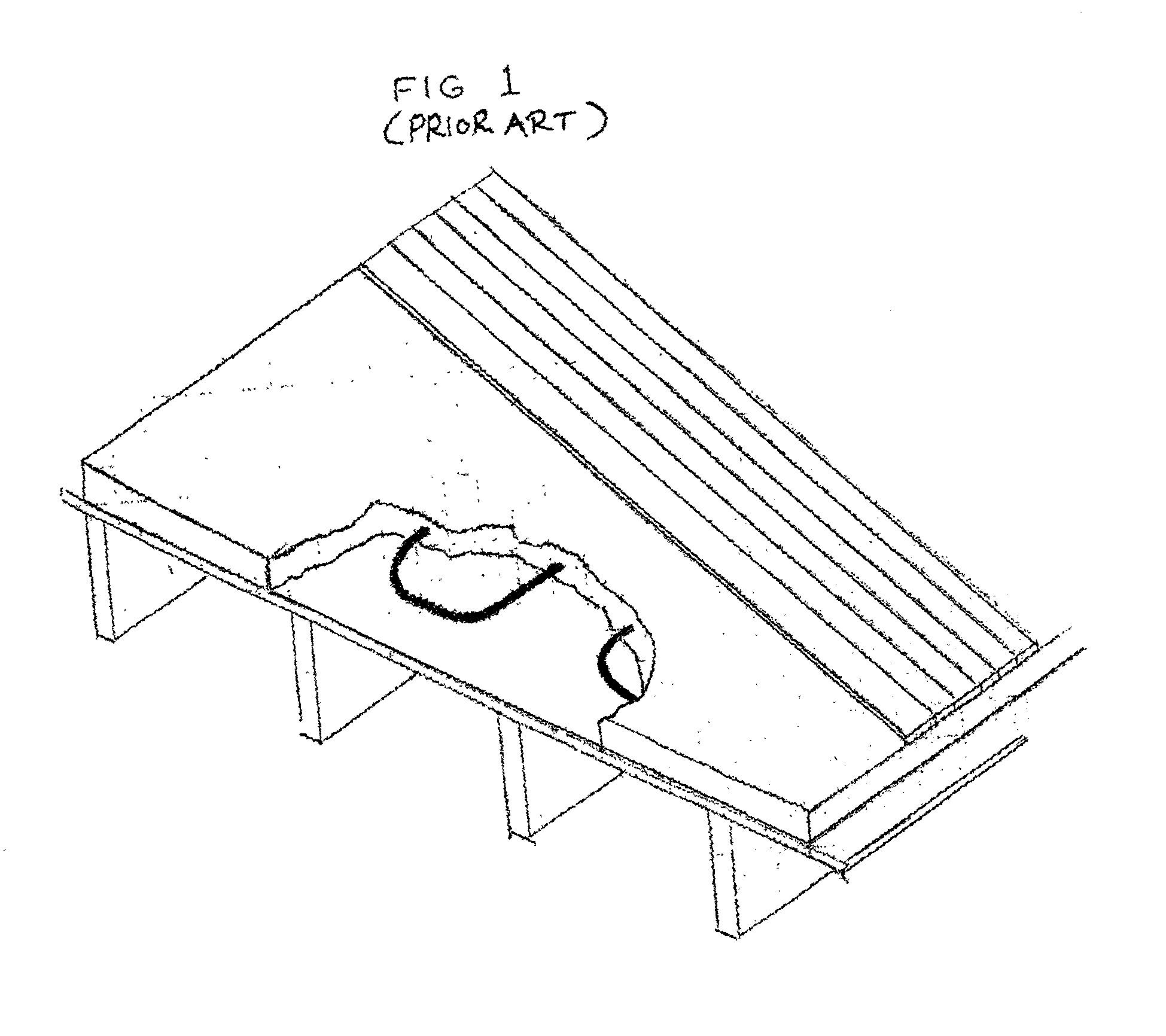
First, the equipment required to pour the concrete slab is extensive and the process for installing the slab involves pumping the concrete through an elaborate delivery system, often at great effort and expense.
Second, delays in construction are necessary to allow the concrete slab to set-up or cure.
Third, the choice of materials that may be used as the thermal slab are limited.
Fourth, the conditions in which the concrete slab cures or is formed varies from job site to job site and is dependent in large part on weather conditions.
This can result in variations in the strength and characteristics of the slab.
Fifth, because the underlayment is a continuous planar slab, if there is leakage in the piping or problems with the subfloor, the entire slab must be removed and replaced.
Sixth, it is often difficult to properly align and then maintain the alignment of the piping when the slab is being poured and is curing.

Method used


Image

  • Modular radiant heat panel system
  • Modular radiant heat panel system
  • Modular radiant heat panel system

Examples


Embodiment Construction

[0071]At the outset, it should be clearly understood that like reference numerals are intended to identify the same structural elements, portions or surfaces, consistently throughout the several drawing figures, as such elements, portions or surfaces may be further described or explained by the entire written specification, of which this detailed description is an integral part. Unless otherwise indicated, the drawings are intended to be read (e.g., cross-hatching, arrangement of parts, proportion, degree, etc.) together with the specification, and are to be considered a portion of the entire written description of this invention. As used in the following description, the terms “horizontal”, “vertical”, “left”, “right”, “up” and “down”, as well as adjectival and adverbial derivatives thereof (e.g., “horizontally”, “rightwardly”, “upwardly”, etc.), simply refer to the orientation of the illustrated structure as the particular drawing figure faces the reader. Similarly, the terms “inw...


PUM


Abstract

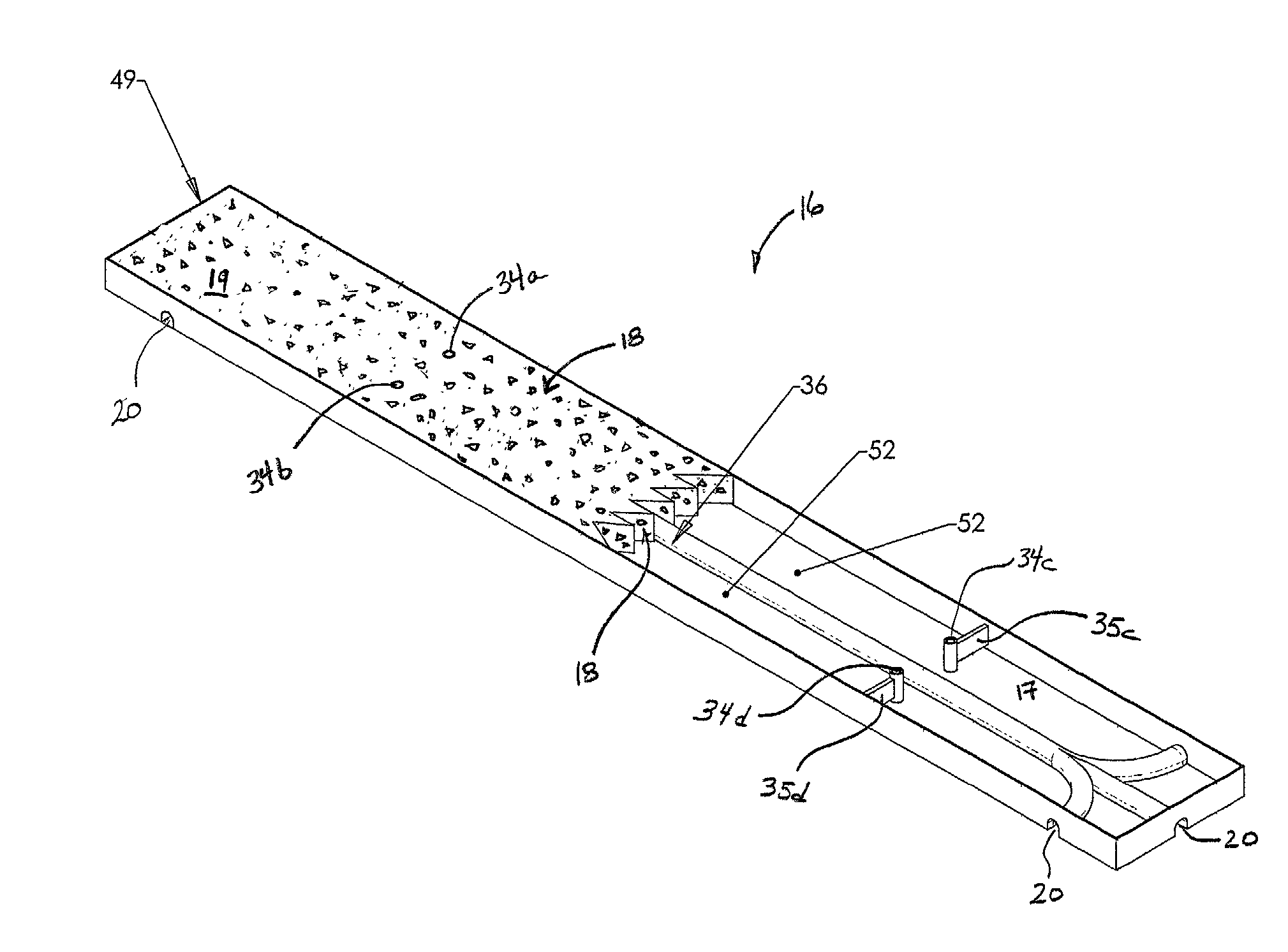
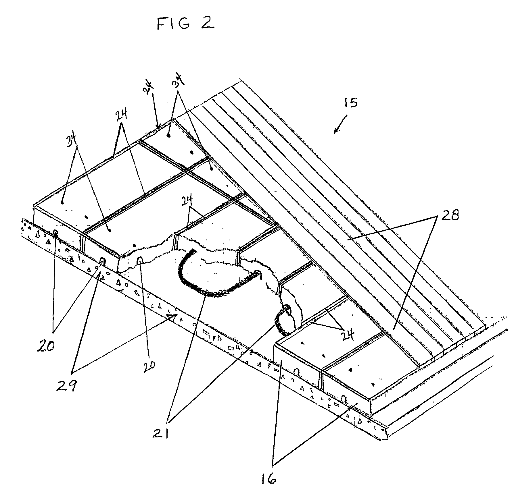
The invention is directed to modular radiant heat panel system. In the preferred embodiment, the system comprises multiple radiant heat transfer panels (16), each of the panels having a thermal mass (18) and a conduit channel (20); a fluid conduit (21), the conduit communicating with an apparatus (23) for heating fluid (22) in the conduit; the multiple panels positioned adjacent each other such that the conduit extends through a series of the conduit channels; the panels, conduit and apparatus so configured and arranged to permit heat transfer from the fluid to the thermal mass of the panel, whereby heat radiates from the panel. The present invention also discloses a radiant heat transfer panel for engagement with a fluid conduit comprising: a formed tray (24); the tray defining a thermal volume (17) and a conduit channel; the volume containing a thermal mass; and the channel, volume and thermal mass configured and arranged to permit heat transfer between the conduit and the thermal mass. The invention also discloses a method for installing a modular radiant heat panel system comprising the steps of: providing an under-layer having a given area (44); providing multiple panels having a thermal mass and a conduit channel; providing conduit; position the conduit over or under the under-layer in a predetermined pattern; and positioning the panels on or under the under-layer such that the conduit extends through at least a portion of the conduit channel of the panels.

Description

TECHNICAL FIELD[0001]The present invention relates generally to the field of in-floor radiant heating systems and, more particularly, to a new modular radiant heat panel system.BACKGROUND ART[0002]Hydronic in-floor radiant heat systems are known in the prior art. Such radiant heating systems utilize tubing within a floor structure to carry and disburse heat through the floor without any visible radiators or heating grills. They generally do so by embedding tubing in a single continuous horizontal concrete slab poured below the finished flooring. Warm water is then circulated through the tubing and the heat in the circulated fluid flowing through the tubing is transferred to the concrete slab by conduction. The concrete stores and radiates the heat, thereby warming objects in the room, rather than the air in the room, which can be more cost effective and can reduce heat loss.[0003]It is known that such systems can be formed by providing a subfloor, running tubing over the subfloor, a...

Claims


Application Information

Patent Timeline
Patent Type & Authority Patents(United States)
IPC IPC(8): E04C2/52F24D3/16
CPCF24D3/142Y02B30/00
Inventor HYDOCK, GARY J.
Owner HYDOCK GARY J
Why Eureka
Try Eureka