Axial piston machine with a swash plate

a technology of axial piston machine and swash plate, which is applied in the direction of mechanical equipment, engines with rotating cylinders, liquid fuel engines, etc., can solve the problems of inapplicability to axial piston machine with variable volume, inability to change the inclination of the swash plate, and inability to use axial piston machine with constant displacement volume, etc., to achieve the effect of improving kinematics, less radial force between the piston and the cylinder, and compact produ

Active Publication Date: 2006-03-21
SA POCLAIN HYDRAULICS B P
View PDF10 Cites 2 Cited by
  • Summary
  • Abstract
  • Description
  • Claims
  • Application Information

AI Technical Summary

Benefits of technology

[0011]With these complementary adjacent first and second driving rotational surfaces the synchronization in rotational movement of the sliding plate with the cylinder block is better achieved as the angular distance between the first and second driving rotational surfaces of each pair of driving rotational surfaces is significantly reduced, which provides a more continuous and smoother meshing and prevents shocks and irregularity of rotational movement of the piston rods when the driving contact is transferred from one piston rod to another one.
[0014]Piston rod pitch diameters (diameters of the circles described by the centers of the first and second spherical joints during the rotation of the cylinder block) are chosen so that the required gap is minimized (see formula thereafter). Then the delay of synchronization between the cylinder block and the sliding plate is also significantly reduced. Consequently, loads in the piston rod decrease and values of Hertzian contact pressures are significantly reduced.
[0015]When being machined the second driving rotational surface and the second spherical joint can be made more easily coaxial than in GB1,140,167 so that the clearance can be smaller. Consequently the rotational angular distance, that is the delay, between the cylinder block and sliding plate can be drastically reduced.
[0018]The sliding plate must be centered with the pump shaft axis when the swash plate angle is equal to zero. To achieve that, the sliding plate is either radially embedded in the swash plate by a radial sliding bearing or is radially guided on its axis of rotation by a centering pivot, which is immovably connected with the sliding plate and is ended by centering spherical joint (e.g. a ball pivot). This ball pivot is slidably guided on the rotation axis of the cylinder block by a centering piston and provides exact radial positioning of sliding plate whatever the swash plate swivelling angle position.
[0020]Thanks to this kinematical layout, the radial forces between the piston and the cylinder are lower with comparison to current solutions. Consequently bushings are not required in the cylinder block even for high working pressure. Pistons and piston rods can be lighter. Thus proposed kinematics provides more compact and lighter product, manufacturing costs are cut, efficiency of energy transmission is increased, and noise, vibration and wear are drastically reduced.
[0021]This kinematics with reduced transmitted forces is also more favorable for the design of a displacement control mechanism and its associated properties.

Problems solved by technology

The disadvantage of this solution is that it is only usable for axial piston machines with a constant displacement volume because the bevels gears engage for a given inclination of the swash plate.
Therefore, the inclination of the swash plate cannot be changed and this solution is not applicable for axial piston machines with a variable displacement volume (cylinder capacity).
Furthermore, the manufacturing of the involved parts generates significant clearance increasing again the delay in synchronization.
Therefore such a design delays the synchronization, generates higher loads in the piston rod and very high Hertzian contact pressures that may bring rapid pitting of the contacting surfaces.

Method used


Image

  • Axial piston machine with a swash plate
  • Axial piston machine with a swash plate
  • Axial piston machine with a swash plate

Examples


Embodiment Construction

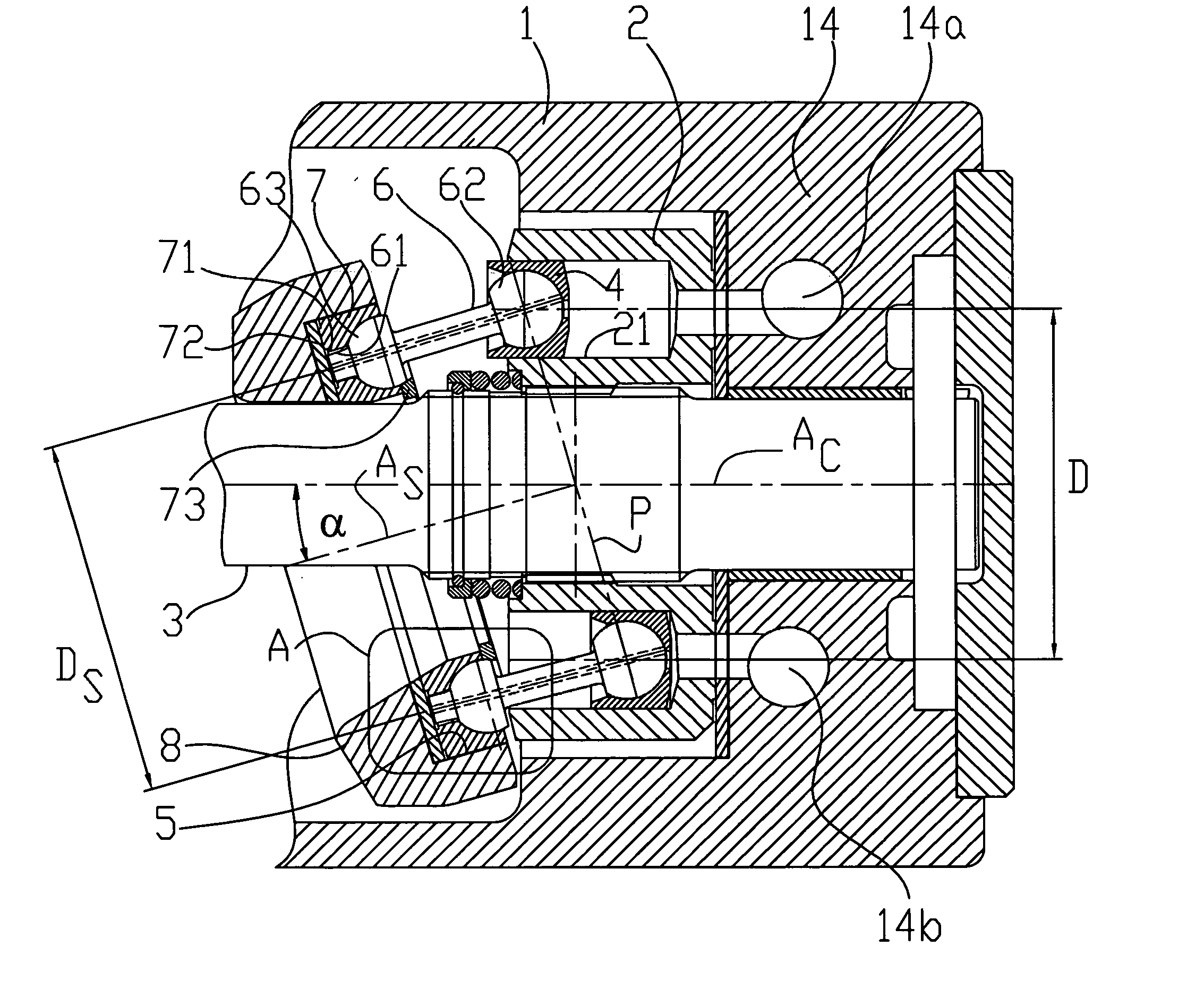
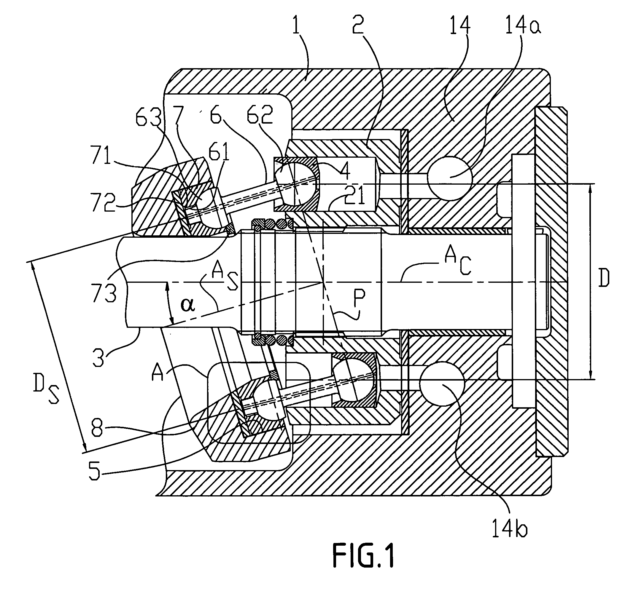
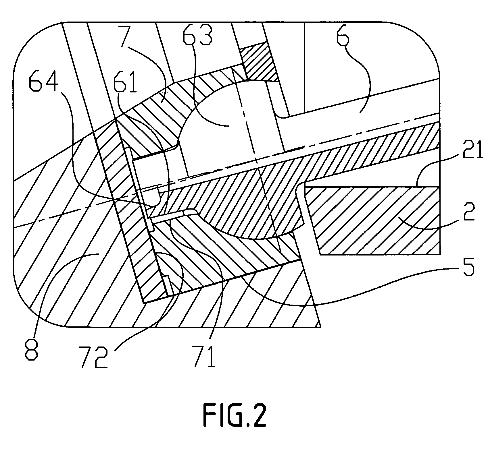
Referring to FIGS. 1 and 2:

[0032]Inside of a case (1) is rotationally supported a shaft (3), which has splines engaging drive splines of a cylinder block (2) comprising a plurality of cylinders (21), in which reciprocate pistons (4). Each piston (4) is pivotally connected to a piston rod (6) by a first spherical joint (62) and each piston rod (6) is connected with a sliding plate (7) by a second spherical joint (63) embedded in the sliding plate, and each piston rod (6) is maintained in the sliding plate (7) by a retaining ring (73) fixed to the sliding plate (7). On the end of each piston rod (6) is created a first driving rotational surface (61), which is close to an axial bearing (72) of the sliding plate (7). In the body of the sliding plate (7) and for each piston rod (6), is created a second driving rotational surface (71), which is adjacent to the first driving rotational surface (61) linked to the piston rod.

[0033]The sliding plate (7) is radially received and supported in a...


PUM


Abstract

The axial piston machine comprises a case, a shaft and a cylinder block (2), arranged so as to rotate in the case and having a plurality of cylinders (21) with pistons, adapted to slide in said cylinders and connected to piston rods (6) by means of first spherical joints, the piston rods being connected to a sliding plate (7) by means of second spherical joints (63), said sliding plate (7) being supported by a swash plate (8) via a bearing (72). For the connection between a piston rod (6) and the sliding plate (7), the machine further comprises a first driving rotational surface (61) linked to the piston rod (6) and a corresponding second driving rotational surface (71) linked to the sliding plate (7), a clearance being left between said first driving rotational surface (61) and said second driving rotational surface (71) and said surfaces being adjacent.

Description

BACKGROUND OF THE DISCLOSURE[0001]This invention generally relates to swash plate type axial piston machines and in particular to any machine with a rotating cylinder block comprising pistons, axial forces of which are transmitted on a swash plate by piston rods connected to a common sliding plate by spherical joints.[0002]DE 40 24 319 discloses a hydraulic machine having a cylinder block with axial pistons and a swash plate supporting a sliding plate. The pistons are connected to piston rods by means of first spherical joints, the piston rods being connected to the sliding plate by means of second spherical joints. The angular position of the cylinder block with respect to the sliding plate is synchronized by a couple of bevel gears, respectively fixedly connected with the cylinder block and with the sliding plate. This bevel gearing can also transmit a portion of the torque developed by this piston machine. The disadvantage of this solution is that it is only usable for axial pist...

Claims


Application Information

Patent Timeline
Patent Type & Authority Patents(United States)
IPC IPC(8): F04B1/22F01B3/00F01B3/02F04B1/12F04B1/20F04B3/00F04B5/00F04B27/08F04D29/44F04D29/66
CPCF01B3/02F04B1/2014F04B1/126F04B1/124
Inventor GALBA, VLADIMIR
Owner SA POCLAIN HYDRAULICS B P
Why Eureka
Try Eureka