Heat pipe evaporator with porous valve

a technology of evaporator and heat pipe, which is applied in the direction of power cables, cables, semiconductor/solid-state device details, etc., can solve the problems of limiting the density and clock speed of electronic systems, increasing power to be dissipated by semiconductor devices, and too low thermal conductivity of available materials

Active Publication Date: 2006-03-21
THERMAL
View PDF50 Cites 66 Cited by
  • Summary
  • Abstract
  • Description
  • Claims
  • Application Information

AI Technical Summary

Problems solved by technology

The ability of prior art thermal management technology to get that waste heat out of semiconductor circuits and into the environment, at a reasonable cost, limits the density and clock speed of electronic systems.
As the power to be dissipated by semiconductor devices increases with time, a problem arises: over time the thermal conductivity of the available materials becomes too low to conduct the heat from the semiconductor device to the atomosphere with an acceptably low temperature drop.
The thermal power density emerging from the semiconductor devices will be so high that even copper or silver spreader plates will not be adequate.
None of the foregoing technologies or devices has proved to be entirely satisfactory.

Method used


Image

  • Heat pipe evaporator with porous valve
  • Heat pipe evaporator with porous valve
  • Heat pipe evaporator with porous valve

Examples


Embodiment Construction

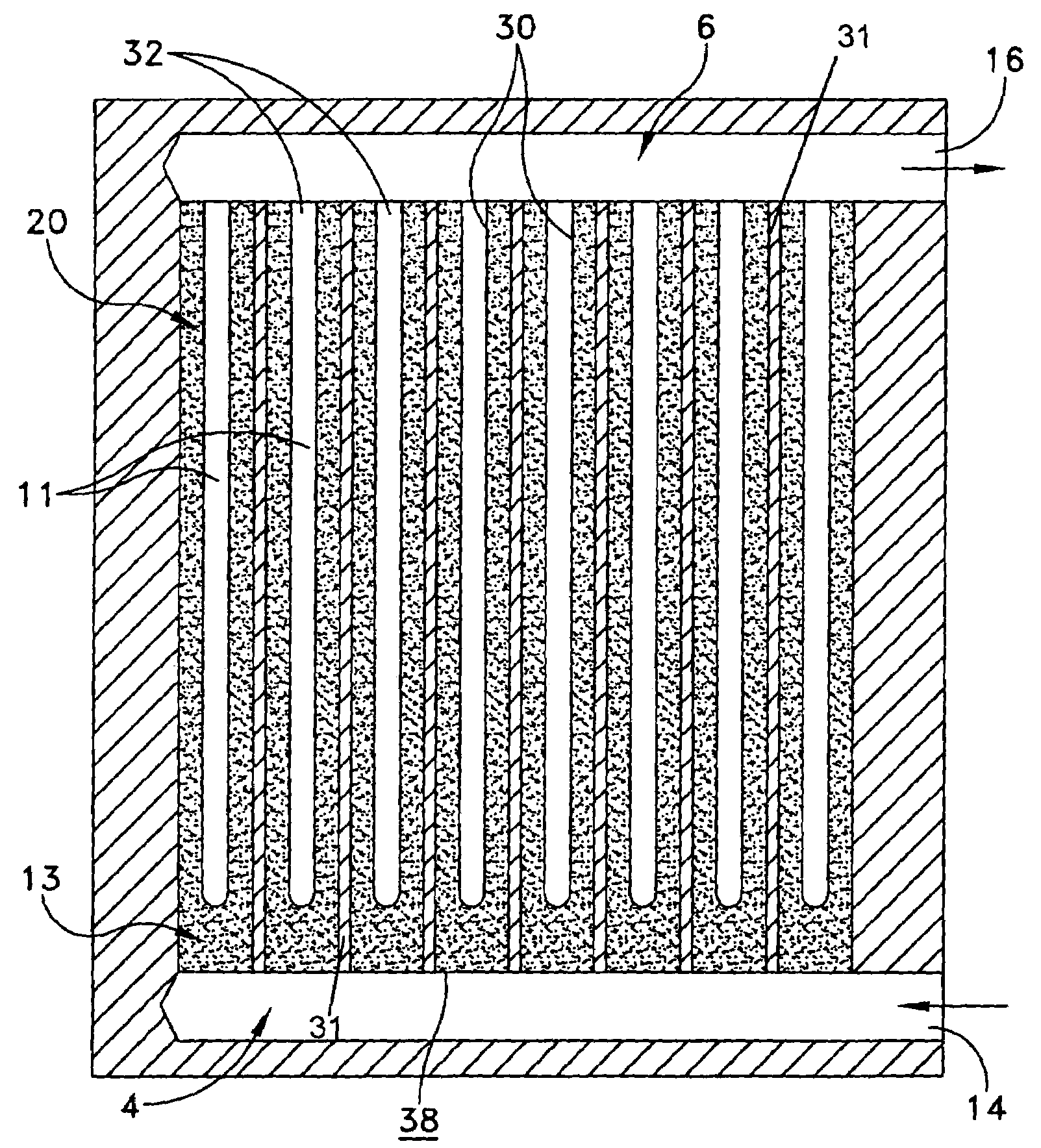
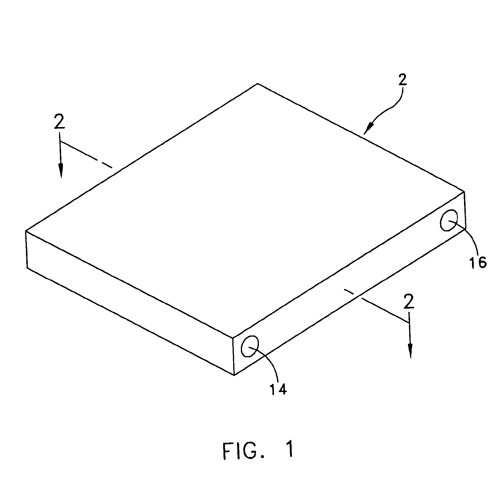
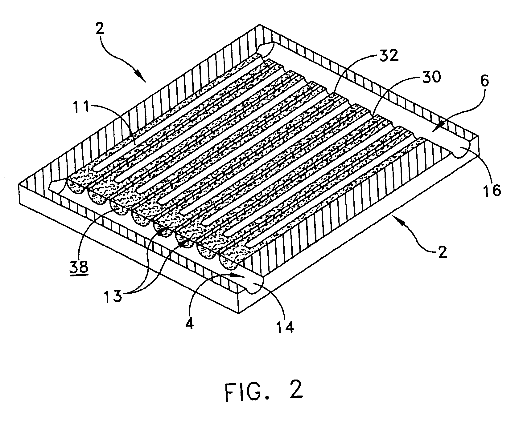
[0021]This description of preferred embodiments is intended to be read in connection with the accompanying drawings, which are to be considered part of the entire written description of this invention. The drawing figures are not necessarily to scale and certain features of the invention may be shown exaggerated in scale or in somewhat schematic form in the interest of clarity and conciseness. In the description, relative terms such as “horizontal,”“vertical,”“up,”“down,”“top” and “bottom” as well as derivatives thereof (e.g., “horizontally,”“downwardly,”“upwardly,” etc.) should be construed to refer to the orientation as then described or as shown in the drawing figure under discussion. These relative terms are for convenience of description and normally are not intended to require a particular orientation. Terms including “inwardly” versus “outwardly,”“longitudinal” versus “lateral” and the like are to be interpreted relative to one another or relative to an axis of elongation, or...


PUM


Abstract

An evaporator includes an enclosure having a fluid inlet manifold and a vapor outlet manifold. At least one blind passageway is arranged within the enclosure so as to open into a portion of the vapor outlet manifold. The interior surface of the enclosure that defines each passageway is covered with a capillary wick. A porous valve is arranged in fluid communication between the fluid inlet manifold and a blind end of the at least one blind passageway.

Description

CROSS-REFERENCE TO RELATED APPLICATIONS[0001]This application claims the benefit of U.S. Provisional Patent Application No. 60 / 499,483, filed Sep. 2, 2003 and U.S. Provisional Patent Application No. 60 / 502,125, filed Sep. 11, 2003.FIELD OF THE INVENTION[0002]The present invention generally relates to evaporators for use in thermal management systems, and more particularly to evaporators utilizing two-phase coolants.BACKGROUND OF THE INVENTION[0003]It has been suggested that a computer is a thermodynamic engine that sucks entropy out of data, turns that entropy into heat, and dumps the heat into the environment. The ability of prior art thermal management technology to get that waste heat out of semiconductor circuits and into the environment, at a reasonable cost, limits the density and clock speed of electronic systems.[0004]A typical characteristic of heat transfer devices for electronic systems is that a semiconductor chip often thermally contacts a passive heat spreader plate, w...

Claims


Application Information

Patent Timeline
Patent Type & Authority Patents(United States)
IPC IPC(8): F28D15/00F25B23/00F25B39/02F28D15/04G01R31/28
CPCF25B23/006G01R31/2886G01R31/2874F28D15/043F25B39/02F28D15/0266
Inventor THAYER, JOHN GILBERTERNST, DONALD M.
Owner THERMAL
Why Eureka
Try Eureka