Brown gas mass production apparatus including a line style electrolytic cell

a gas mass production and electrolysis cell technology, applied in the direction of electrolysis components, manufacturing tools, instruments, etc., can solve the problems of inability to achieve sufficient electrolysis efficiency with conventional gas generators, inability to occurrence of electrolysis at predetermined portions, and failure to put the method of electrolysis water to practical use, so as to improve electrolysis efficiency speed up the speed of speed

Inactive Publication Date: 2006-03-21
KIM SANG NAM
View PDF9 Cites 29 Cited by
  • Summary
  • Abstract
  • Description
  • Claims
  • Application Information

AI Technical Summary

Benefits of technology

[0021]To solve the above problems, the present inventor has made various studies. And as a result, he has found that the height of the surface of the electrolyte in a line style electrolytic cell has great influence on the amount of gas generation, and if the electrolytic cell case is made of an insulation material, electrolysis efficiency can be improved. Accordingly, the present invention is, as being different from the cited references, to provide a Brown gas mass production apparatus including a line style electrolytic cell wherein the top surface of the electrode unit is opened to make bubbles flow at a relatively rapid speed such that electrolysis efficiency can be more improved.
[0022]Another object of the present invention is to provide a Brown gas mass production apparatus including a line style electrolytic cell wherein the electrolytic cell case, the side plates of the electrode unit and the insulation bars are molded by an insulation material, thereby improving electrolysis efficiency, and the side plates and the insulation bars are provided, thereby enhancing efficiency in an assembling work.
[0023]Still another object of the present invention is to provide a Brown gas mass production apparatus including a line style electrolytic cell in which an automatic feed water device, a forced electrolyte circulating and cooling device and an electrolyte distributing and discharging pipe are efficiently disposed as auxiliary devices for the purpose of maintaining the surface of the electrolyte constantly and promoting a smooth discharge of the gas, thereby generating a large quantity of Brown gas.
[0026]According to the present invention, the electrode units are disposed in the electrolytic cell case, the automatic feed water device is operated according to the lever sensor installed in the auxiliary tank connected to the electrolytic cell in order to maintain the surface of the electrolyte at a predetermined level such that a relatively large horizontal space is formed just above the top surfaces of the electrode units. The forced electrolyte cooling and circulation device serves to maintain the electrolyte at a predetermined temperature. The electrolyte distributing and discharging pipe serves to accelerate the flow of the bubbles, and a backfire preventing device serves to prevent the backfire of the Brown gas generated from the horizontal space in the electrolytic cell case, such that the Brown gas can be stably supplied to a burner.

Problems solved by technology

However, the method of electrolyzing water has failed to be put to practical use because it is predominantly recognized as being not economical, such that it has been applied only for laboratory work like soldering or welding.
In the case of producing the Brown gas in large quantities, this is clearly proved, and therefore, it can be appreciated that we cannot expect to obtain a sufficient efficiency with conventional gas generators.
This temporarily makes the occurrence of the electrolysis impossible at the predetermined portions on which the bubbles are attached.
This causes efficiency of the gas generation to be substantially reduced.
As can be seen from the conventional electrode unit disclosed in cited references, the electrode unit does not have any insulation bar interposed between the electrode plates and is also configured to fix the upper and lower fixing bars only by using stay bolts, without any side plates, which makes the sides thereof completely opened so that an insulation is not accomplished.
This results in the loss of an electric current, and thus, an electrolysis efficiency is considerably reduced.
However, this process is complicated and, since a predetermined water pressure exists in the electrode unit, the staying time of the bubbles generated between the electrode plates becomes longer, thereby greatly reducing electrolysis efficiency.

Method used


Image

  • Brown gas mass production apparatus including a line style electrolytic cell
  • Brown gas mass production apparatus including a line style electrolytic cell
  • Brown gas mass production apparatus including a line style electrolytic cell

Examples


Embodiment Construction

[0037]Reference will now be made in detail to the preferred embodiments of the present invention, examples of which are illustrated in the accompanying drawings.

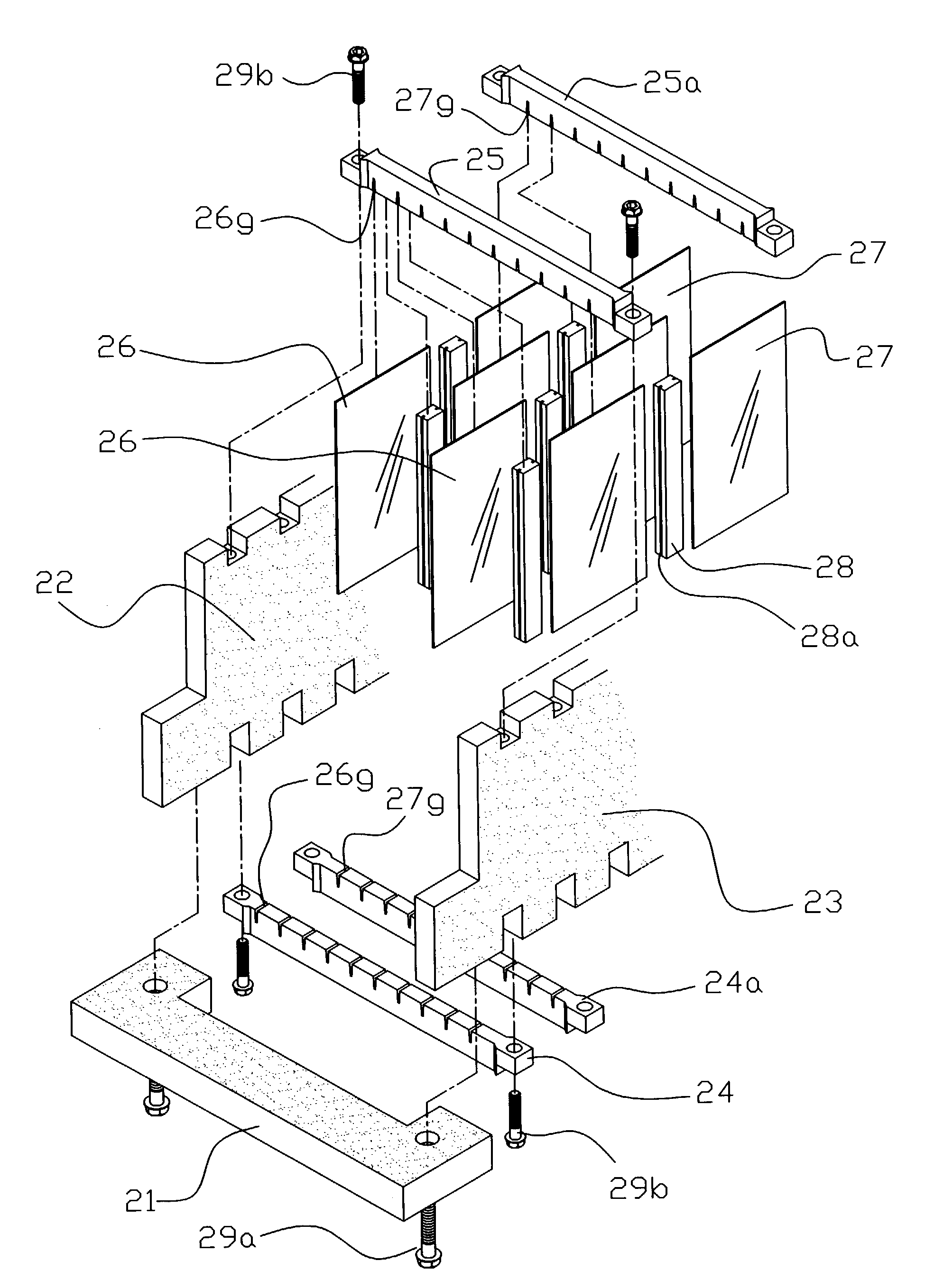
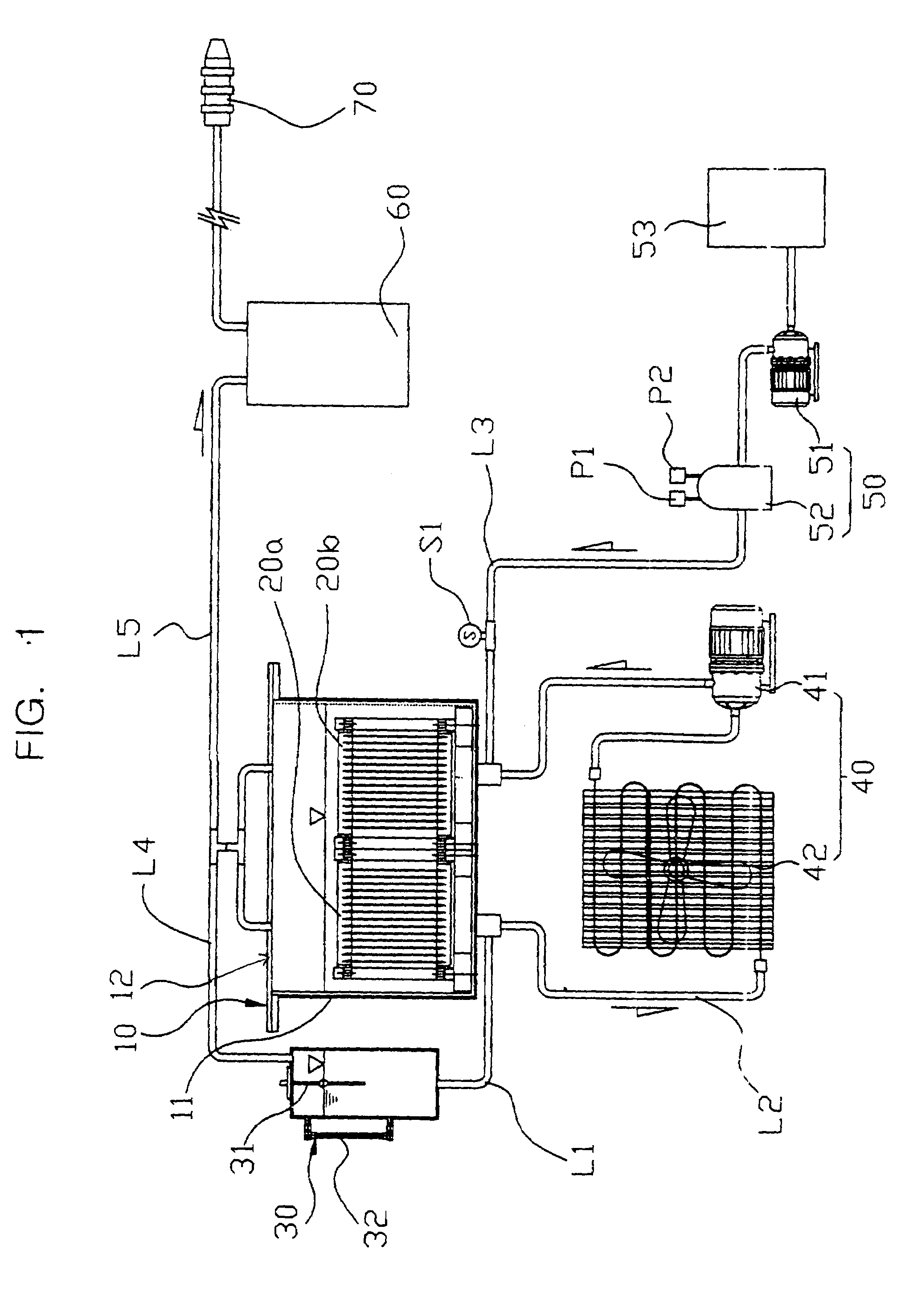
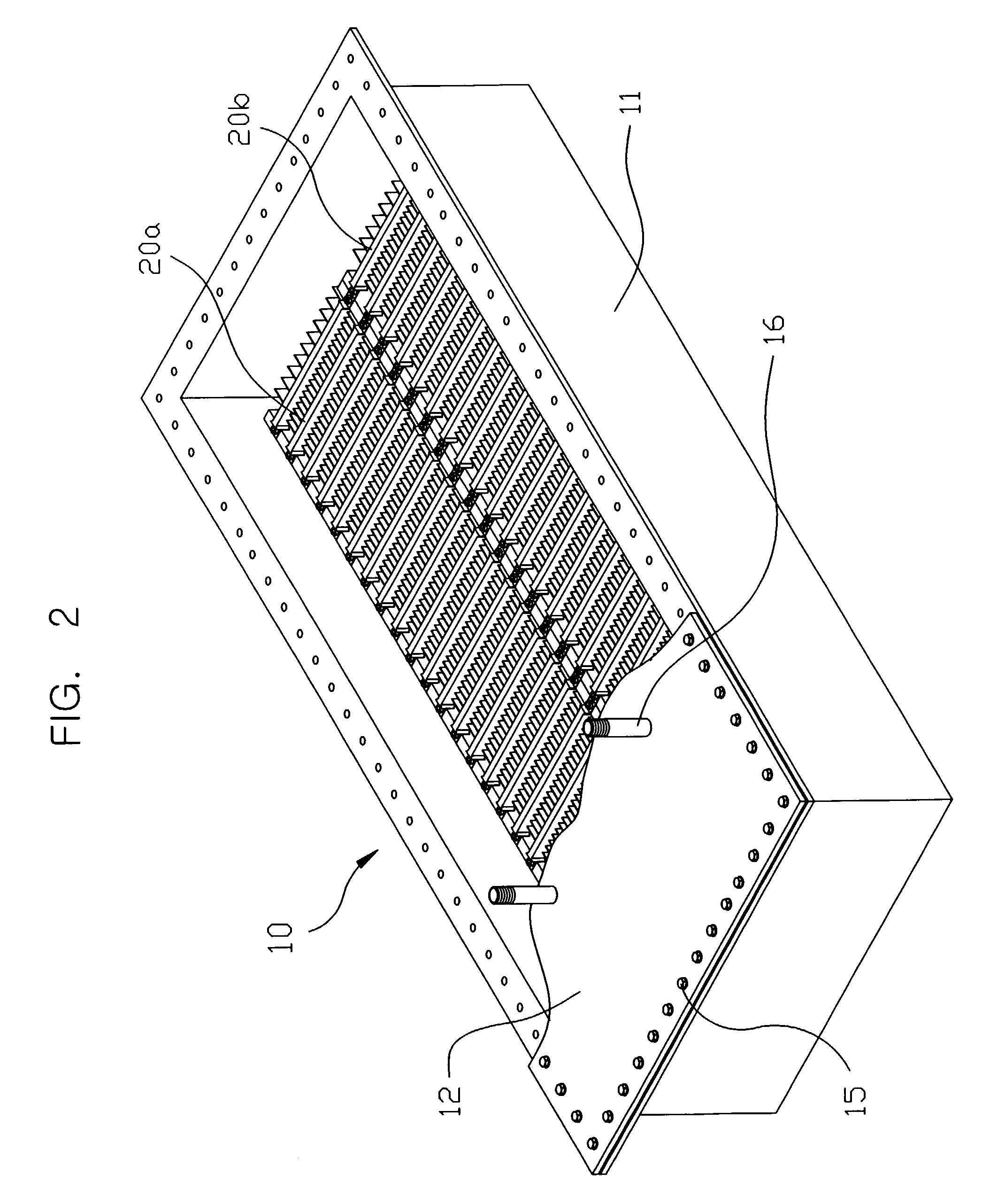
[0038]FIG. 1 is a systematic view illustrating the whole configuration of a Brown gas mass production apparatus, including a line style electrode cell according to the present invention. FIG. 2 is a perspective view illustrating an electrolytic cell case having built-in electrode units that is one component of the present invention. FIG. 3 is a perspective view illustrating the whole configuration of the electrode unit in an assembled state according to the present invention. FIG. 4 is an exploded perspective view of the electrode unit of FIG. 3. FIG. 5 is a plan view illustrating the connection state of the electrode unit with a power supply. FIG. 6 is a perspective view illustrating an auxiliary tank having a level sensor installed therein. FIG. 7 is a perspective view illustrating an electrolyte discharging pipe.

[0039]As ...


PUM

PropertyMeasurementUnit
angleaaaaaaaaaa
surface levelaaaaaaaaaa
temperatureaaaaaaaaaa

Abstract

Disclosed is a Brown gas mass production apparatus having a line style electrolytic cell in which an electrolytic cell case having an electrolyte distribution and discharging pipe mounted on the inside bottom surface thereof is coated with insulation material on the inner surface thereof, electrode units are disposed by two or three groups in a side-by-side arrangement in the electrolytic cell case, an electrolytic cell upper plate having gas outlet nipples mounted thereon is sealingly coupled to the top surface of the cell case to form a secured sealing between edges of the upper plate and the cell case. The line style electrolytic cell further includes an auxiliary electrolyte tank connected to the electrolytic cell case for maintaining the surface of the electrolyte at a predetermined level just above the top surface of the electrode units in the electrolytic cell according to the operation of a solenoid valve, so that water is automatically fed into the electrolytic cell according to the opening and closing operation of a solenoid valve operated by a level sensor installed in the auxiliary electrolyte tank, and a relatively large horizontal space is formed just above the top surface of the electrode units, so that gas and water are separated directly at the horizontal space.

Description

BACKGROUND OF THE INVENTION[0001]1. Field of the Invention[0002]The present invention relates to a Brown gas mass production apparatus including a line style electrolytic cell. This is an essential component to use Brown gas as fuels in industrial boilers, furnaces, and so on, and more particularly, to a Brown gas mass production apparatus including a line style electrolytic cell in which insulation bars are interposed between (−) and (+) electrode plates in order to enhance the total electrolysis efficiency. The (−) and (+) electrode plates are crosswisely aligned to face each other in their half area, respectively, while also being lengthwisely alternately arranged to be overlappingly disposed to each other. They are then attached to a predetermined frame, constructed of left and right plates which are made of an insulation material, by securely fitting upper and lower fixing bars into generally square grooves of the left and right plates, such that the electrode plates can be for...

Claims


Application Information

Patent Timeline
Patent Type & Authority Patents(United States)
IPC IPC(8): C25B1/06C25B9/00C25B9/17C25B15/00
CPCC25B1/06C25B15/00C25B9/06Y02E60/366Y02E60/36C25B1/04C25B11/00C25B9/17
Inventor KIM, SANG-NAM
Owner KIM SANG NAM
Why Eureka
Try Eureka