Check patentability & draft patents in minutes with Patsnap Eureka AI!

Process for making a curved PI shaped preform made from woven composite materials

a composite material and preform technology, applied in the field of composite structure fabrication techniques, can solve the problems of severe distortion, the strength of the joint depends on the layers of the composite cloth, etc., and achieve the effect of reducing the strength of the preform

Active Publication Date: 2006-03-21
NORTHROP GRUMMAN SYST CORP
View PDF5 Cites 18 Cited by
  • Summary
  • Abstract
  • Description
  • Claims
  • Application Information

AI Technical Summary

Benefits of technology

[0007]It is a further object of the invention to provide a process for making such 3D woven...

Problems solved by technology

The disadvantage is that the joint's strength is dependent on the layers of composite cloth.
However, attempts to use such a preform in a curved structure has resulted in severe distortion.

Method used


Image

  • Process for making a curved PI shaped preform made from woven composite materials
  • Process for making a curved PI shaped preform made from woven composite materials
  • Process for making a curved PI shaped preform made from woven composite materials

Examples


Embodiment Construction

[0027]The typical PI woven preform is illustrated in FIGS. 1 and 2, indicated by numeral 10. The preform 10 includes upstanding legs 12 and 14 and bottom foot portions 16 and 17, with center or root 18. The warp fibers 20 run parallel to the legs 12 and 14, while the fibers 21 run perpendicular to the upstanding legs. If one tries to form a curve, indicated by arrows 22A and 22B, the legs 12 and 14 tend to bend over indicated by arrow 24. Attempts to “bend” the preform 10 into other shapes also cause one or more portions to warp. The subject process will eliminate this problem.

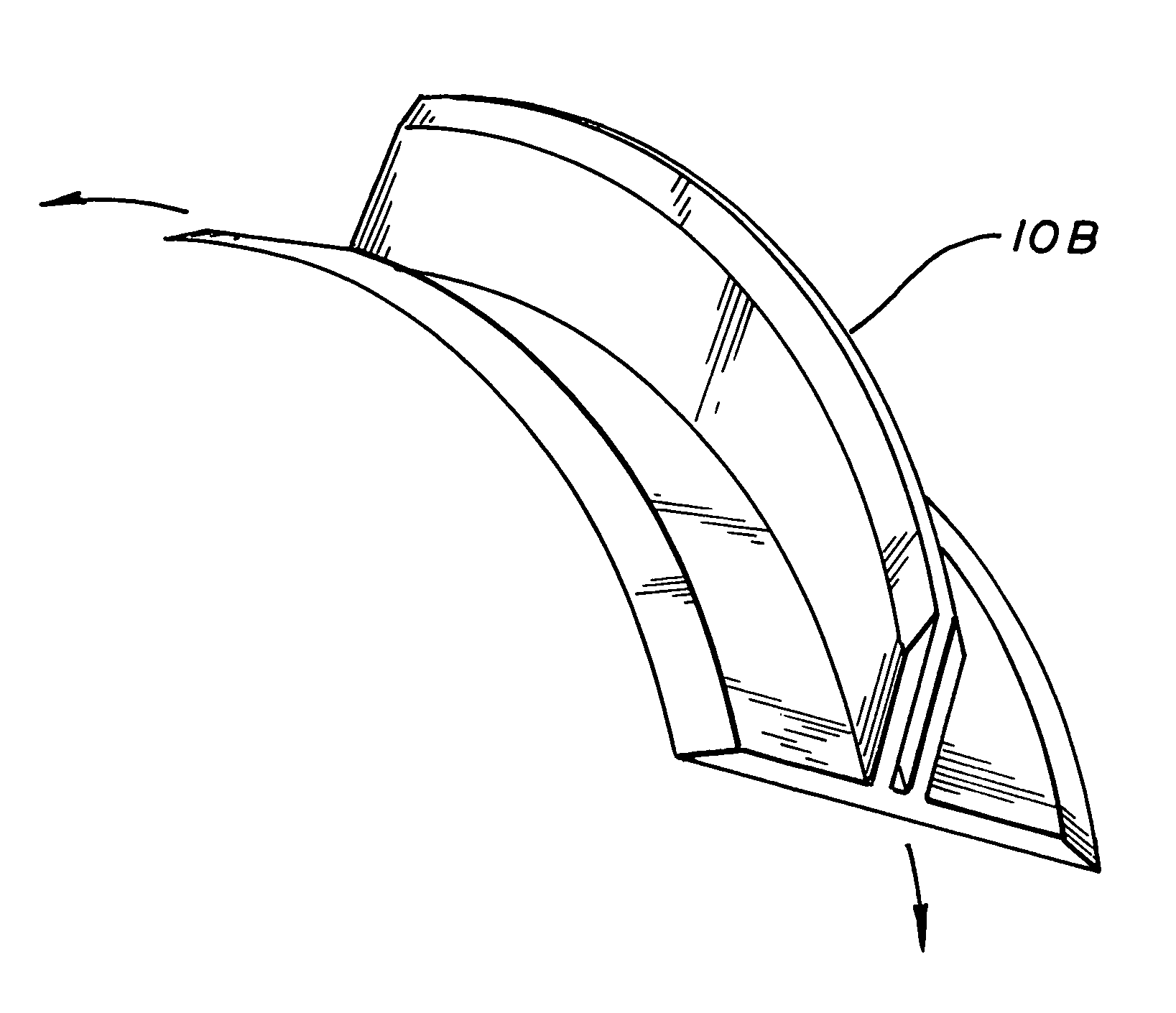
[0028]A completed preform 10A is shown in FIG. 3, having a curved length 26, with a radius 28. To accomplish this, the upstanding legs 12 and 14 are pushed over onto the one of the bottom portions 16 or 17 as shown in FIG. 14. The folded preform is then placed in the die 30 shown in FIG. 4 which includes a cutter head 31 and receiver pad 32. The cutter head 31 incorporates staggered blades 33 having a width 34...


PUM

PropertyMeasurementUnit
Lengthaaaaaaaaaa
Angleaaaaaaaaaa
Moldableaaaaaaaaaa

Abstract

The invention is a process for forming a 3D woven PI shaped cross-section preform having a first and second bottom foot portions and first and second upstanding leg portions for use in a structure having at least one curved portion of a specific length. In detail, the process includes the steps of: 1) cutting the treads parallel to the direction of curvature into over a length equal to the length, such that the cuts in each thread are spaced from the cuts in the adjacent treads; 2) stretching the portions of the preform requiring curvature; and 3) forming the curvature in the preform.

Description

BACKGROUND OF THE INVENTION[0001]1. Field of the Invention[0002]The invention relates to the field of composite structure fabrication techniques and, in particular, to a process for forming curves in woven composite preforms.[0003]2. Description of Related Art[0004]Typically T shaped composite structures are fabricated by joining the vertical member to the horizontal member by bonding a multi-number of reinforcing sheets across the joint (extending from the horizontal member up along the side of the vertical member). Such a joint is disclosed in WIPO Publication WO 01 / 64387 A1 Production, Forming, Bonding Joining And Repair Systems For Composite And Metal Components by N. Graham. Two honeycomb sheets are joined by layers of composite cloth to the horizontal member on each side of the vertical member that extend up each side of the vertical member. The disadvantage is that the joint's strength is dependent on the layers of composite cloth.[0005]Recently, three-dimensional weaving has...

Claims


Application Information

Patent Timeline
IPC IPC(8): B29C70/46B29C43/14
CPCB29B11/16B29C43/021B29K2105/0854
Inventor REIS, CARL ANDREWDECKER, DOUGLAS DEANHUSMANN, CHRISTOPHER H.
Owner NORTHROP GRUMMAN SYST CORP
Features
  • R&D
  • Intellectual Property
  • Life Sciences
  • Materials
  • Tech Scout
  • Unparalleled Data Quality
  • Higher Quality Content
  • 60% Fewer Hallucinations
Learn More