Light source device, method of producing the same, and display apparatus

a technology of light source device and discharge tube, which is applied in the direction of discharge tube main electrodes, lighting and heating apparatus, instruments, etc., can solve the problems of insufficient contact between the heat conductive member (the heat conductive rubber cap) and the discharge tube, and the temperature rise in the vicinity of the discharge tube electrodes is particularly large, so as to achieve the stabilization of the luminance level of the entire discharge tube

Inactive Publication Date: 2006-03-21
SHARP KK
View PDF13 Cites 9 Cited by
  • Summary
  • Abstract
  • Description
  • Claims
  • Application Information

AI Technical Summary

Benefits of technology

[0037]With this display apparatus, the local cooling can be effectively performed on t

Problems solved by technology

The temperature rise in the vicinity of the electrodes of the discharge tubes is particularly large.
Such a decrease of visible ray emission causes a problem in maintaining the luminance level of the backlight.
However, the contact between the heat conductive members (the heat conductive rubber caps) and the discharge tubes is often insufficient, as shown in FIG. 2.
Because of the insufficient contact, sufficient cooling effects cannot be obtained, resulting in a temperature rise in the neighboring area of the electrodes up to 130 or 140° C.
When a stress exits between the harness and the discharge tubes, cracks devel

Method used


Image

  • Light source device, method of producing the same, and display apparatus
  • Light source device, method of producing the same, and display apparatus
  • Light source device, method of producing the same, and display apparatus

Examples


first embodiment

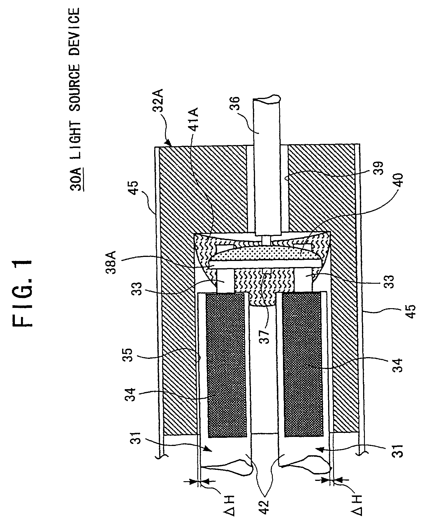
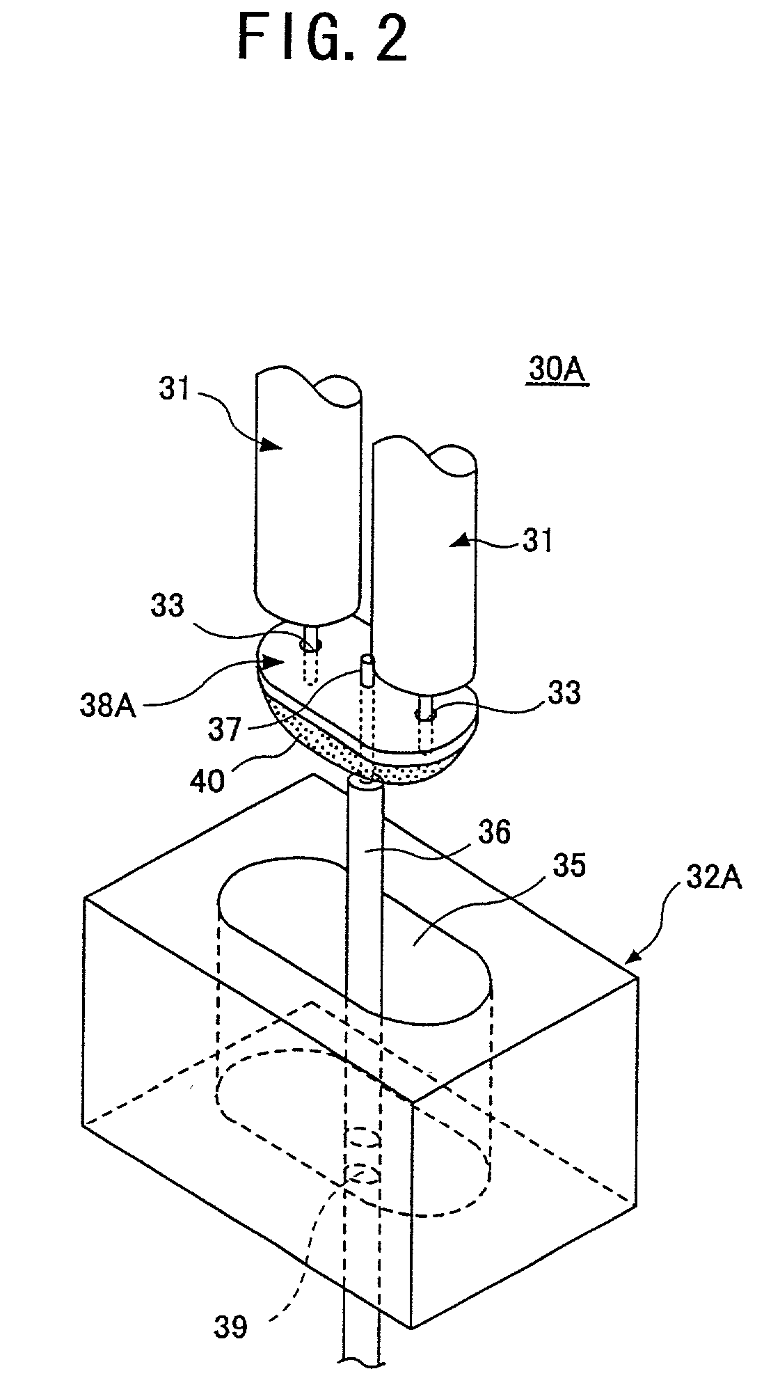
[0072]FIGS. 1 through 3 illustrates a light source device 30A, which is the present invention, and a liquid crystal display unit 10 (which is a display device) equipped with the light source device 30A.

[0073]Referring first to FIG. 3, the liquid crystal display unit 10, onto which the light source device 30A is mounted, will now be described. The liquid crystal display unit 10 includes a liquid crystal panel 11, a decorative laminate 12, a light guide plate 14, a carriage frame 17, a back face panel 18, and the light source device 30A.

[0074]The liquid crystal panel 11 includes a liquid crystal panel main body 25 that displays texts and images, and drivers 26 that surround the liquid crystal panel main body 25 and drive the liquid crystal panel main body 25. The decorative laminate 12 is placed on the liquid crystal panel 11.

[0075]The decorative laminate 12 is made of a metallic material, such as stainless steel (SUS), iron, or aluminum, or a resin material. The decorative laminate 1...

second embodiment

[0104]Referring now to FIG. 4, the present invention will be described.

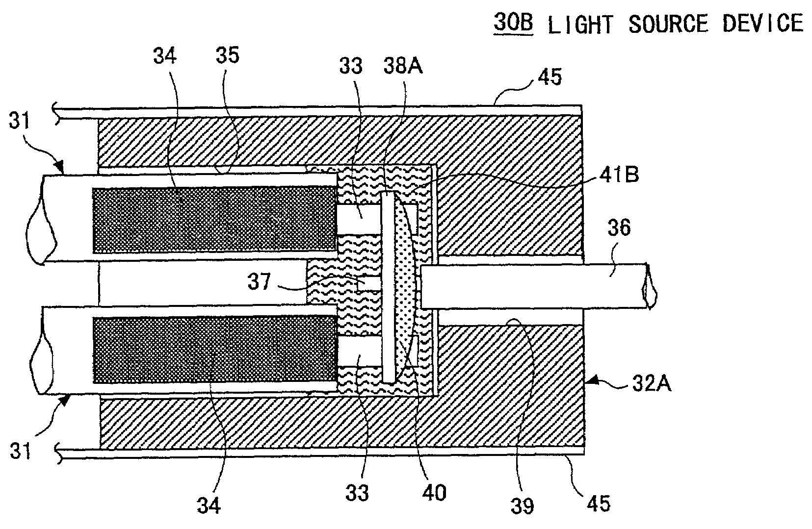
[0105]FIG. 4 shows a light source device 30B in accordance with the second embodiment of the present invention. In FIG. 4, the same components as in FIGS. 1 through 3 are denoted by the same reference numerals as in FIGS. 1 through 3, and explanations for those components are omitted from the description below. The same applied to the descriptions of all other embodiments that will follow this embodiment.

[0106]The light source device 30B according to this embodiment is characterized by having the bottomed opening 35 filled with a low heat conductivity member 41B made of a silicone oil compound (such as G750 having a heat conductivity of 1.5 W / K / m, produced by Dow Corning Toray Silicone Co., Ltd.), instead of the low heat conductivity member 41A employed in the light source device 30A according to the first embodiment.

[0107]This silicone oil compound has a higher (Note: Should not this be “lower”?) viscosity, comp...

third embodiment

[0110]Referring now to FIGS. 5A through 5C, the present invention will be described.

[0111]FIGS. 5A through 5C illustrate a light source device 30C in accordance with the third embodiment of the present invention. The light source device 30C according to this embodiment does not employ the heat conductive member 32A used in the first and second embodiments. Instead, the discharge tubes 31 are fixed to the reflector 45 by a first spacer 46A, and the wire harness 36 is also fixed to the reflector 45 by a second spacer 47A. Furthermore, a low heat conductivity member 41C fills the space between the first spacer 46A and the second spacer 47A.

[0112]The first spacer 46A and the second spacer 47A are plate-like members formed by molding silicone resin, for instance. As shown in FIG. 5B, the first spacer 46A has two holding holes 48 into which the discharge tubes 31 are inserted and held therein. As shown in FIG. 5C, the second spacer 47A has holding holes 50 into which the electrode termina...


PUM


Abstract

The present invention relates to a light source device including discharge tubes that emit light by discharging in a thin atmosphere, a method of producing the light source device, and a display apparatus in which the light source device is employed. This light source device includes discharge tubes and a heat conductive member that is brought into contact with the neighboring area of the electrodes of the discharge tubes so as to locally cool down the neighboring area of the electrodes. In the light source device, a low heat conductivity member having lower heat conductivity than the heat conductive member is interposed between the heat conductive member and the discharge tubes. With such a structure, the luminance in the entire light source device can be increased and made uniform, and the reliability of the light source device can be increased accordingly.

Description

BACKGROUND OF THE INVENTION[0001]The present invention generally relates to light source devices, methods of producing the light source devices, and display apparatuses, and, more particularly, to a light source device provided with discharge tubes that discharge electricity to emit light in a thin atmosphere, a method of producing such a light source device, and a display apparatus utilizing such a light source device.[0002]Conventionally, the backlight of a display apparatus such as a liquid display apparatus is formed with a light source device that includes one or a plurality of discharge tubes and a reflector. The discharge tubes are cold cathode tubes, in which mercury is sealed in Ar gas or Ne gas. A fluorescent material is applied to the walls of the discharge tubes. The mercury gas generates ultraviolet rays during electric discharge, and the ultraviolet rays impinging onto the fluorescent material cause visible rays.[0003]Most of the backlights of conventional liquid cryst...

Claims


Application Information

Patent Timeline
IPC IPC(8): H01J1/02F21V29/00F21Y103/00G02F1/13357H01J5/16H01J5/54H01J61/52
CPCH01J61/523H01J5/16H01J5/54G02F1/133604G02F1/133608G02F2001/133612G02F2001/133628G02F1/133612G02F1/133628G02F1/1335
Inventor KOBAYASHI, TETSUYAHAYASHI, KEIJIYONEMURA, KOSHUYAMADA, FUMIAKIKAIWA, KAZUMASATAKAHASHI, HIROYOSHISUZUKI, TOSHIHIROGOTOH, TAKESHIHAMADA, TETSUYASUGAWARA, MARIHAYASHIMOTO, SEIJI
Owner SHARP KK
Why Eureka
Try Eureka