Module support for electrical/electronic components

a technology for electronic components and modules, applied in the direction of electrical apparatus casings/cabinets/drawers, electrical apparatus construction details, casings/cabinets/drawers details, etc., can solve the problems of damage to the insulation sheathing of the module frame, and achieve the effect of improving the quality of soldering, small thermal conduction cross section, and simple and inexpensiv

Inactive Publication Date: 2006-03-21
ROBERT BOSCH GMBH
View PDF15 Cites 6 Cited by
  • Summary
  • Abstract
  • Description
  • Claims
  • Application Information

AI Technical Summary

Benefits of technology

[0003]Using the module frame according to an embodiment of the present invention, the heat transmitted to the contact segments of a module frame, in soldering in particular, is not allowed to flow unhindered to the parts of the conductor structure surrounded by the insulation sheathing. Due to the special design of the electric conductors in the continuous cutouts of the module frame, heat may flow only through connecting webs having a smaller thermal conduction cross section. The connecting webs throttle the heat flow to the segments of the pressed screen surrounded by the insulation sheathing. Damage to the module frame when the contact segments of the metallic conductors are heated to a high temperature may thus be prevented to advantage. In addition, in soldering the connecting elements of a component to the contact segments of the conduction screen in particular, the process heat required for soldering remains at the soldering point. Therefore, selective soldering of the individual solder points may be achieved with small solder pots or solder dies to advantage, which results in a definite improvement in soldering quality. The connecting elements of electronic components may be soldered to the contact segments in one method step to advantage. The structural design of the contact regions of the module frame is manufacturable in a simple and inexpensive manner without any increased expense.
[0004]In an embodiment of the present invention the contact segments of the conductor structure are designed in the form of soldered eyelets having a central opening for passing through one connecting element of an electric / electronic component for each eye. This measure makes it possible to mount the component on the module frame in a procedure similar to that used in the production of circuit boards, where the connecting elements of a component are inserted into the openings of the soldered eyelets and may then be soldered.
[0005]In another embodiment the at least one connecting web by which the contact segment is connected to the conductor structure is bent up out of the plane of the conductor structure, so that the contact segment is situated inside or outside the cutout in a plane parallel to the plane of the conductor structure. This greatly facilitates soldering of the connecting elements of a component. Due to the bending of the connecting web, it is possible in particular to achieve a complete immersion of the contact segment in the solder pot in particular in selective soldering using a solder pot, and thus it is possible to improve soldering quality.
[0006]In another embodiment the at least one connecting web is bent by deep drawing. This ensures, first of all, that the contact segment is bent into a defined position while the tapering of the thermal conduction cross section of the at least one connecting web produced by deep drawing further increases the effect of same as a poor heat conductor.

Problems solved by technology

One disadvantage of the known module frames having a pressed screen is that the heat transmitted from the contact segments directly to the segments of the metallic conductors surrounded by the insulation sheathing is capable of damaging the insulation sheathing of the module frame.

Method used


Image

  • Module support for electrical/electronic components
  • Module support for electrical/electronic components
  • Module support for electrical/electronic components

Examples


Embodiment Construction

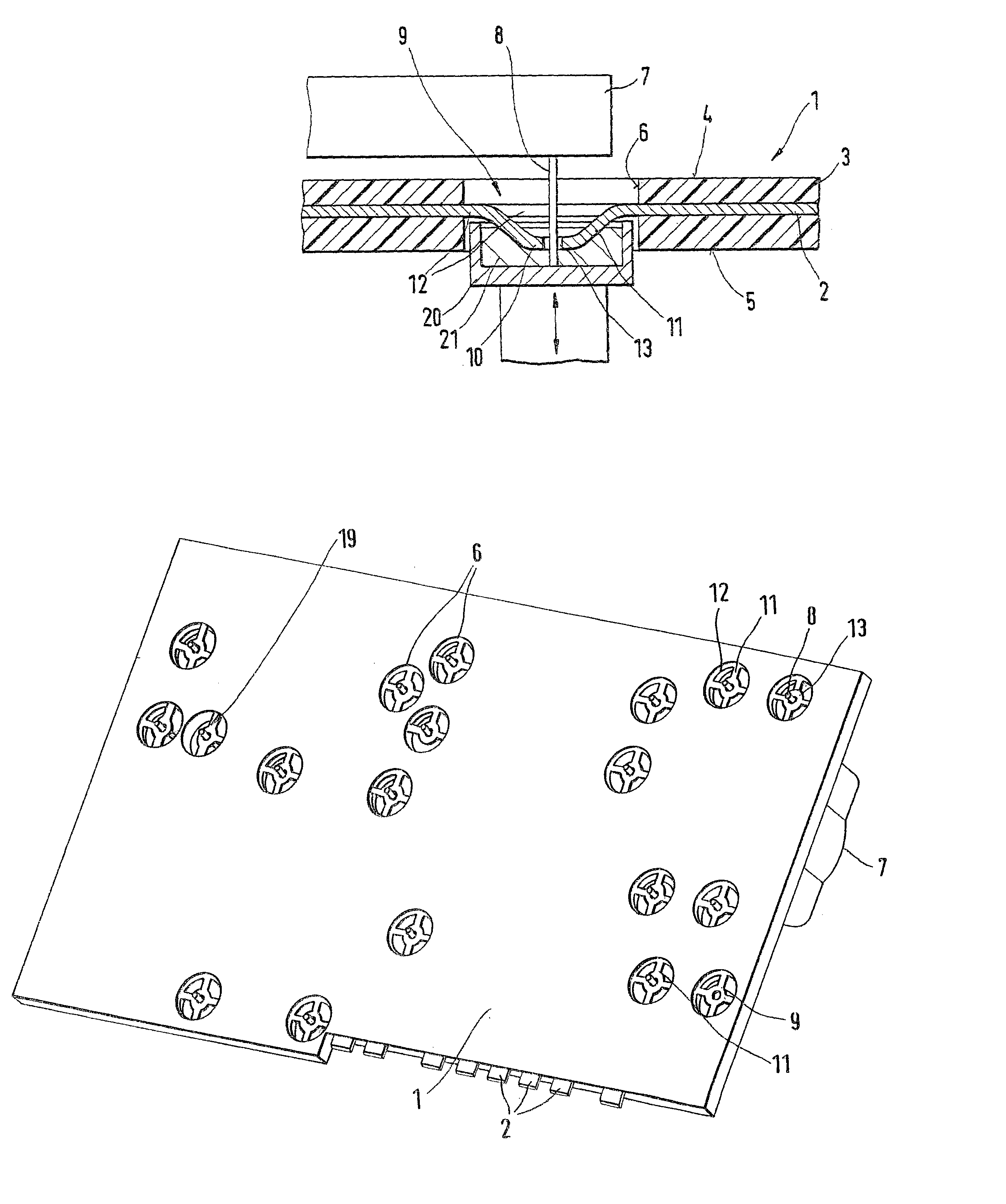
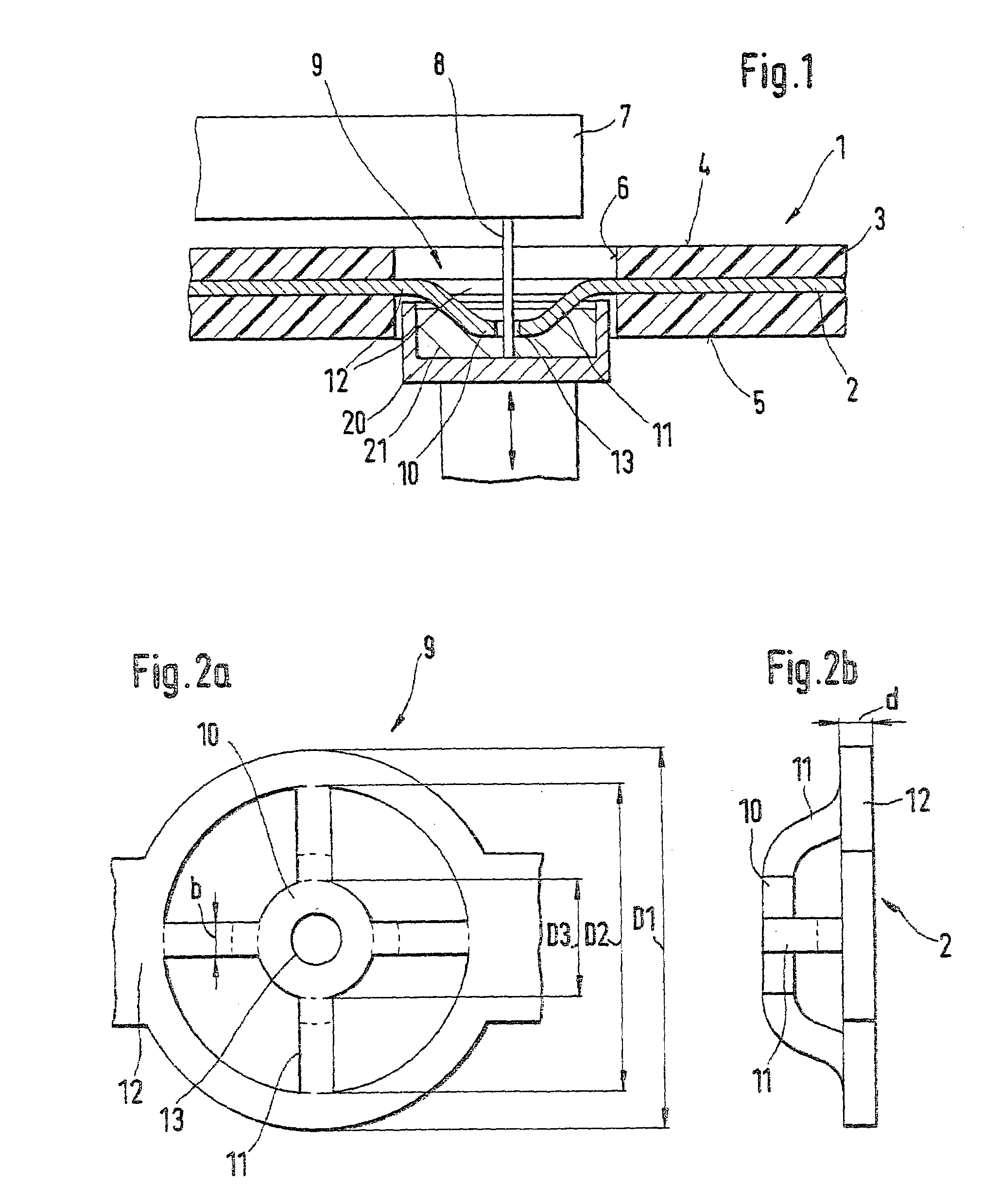
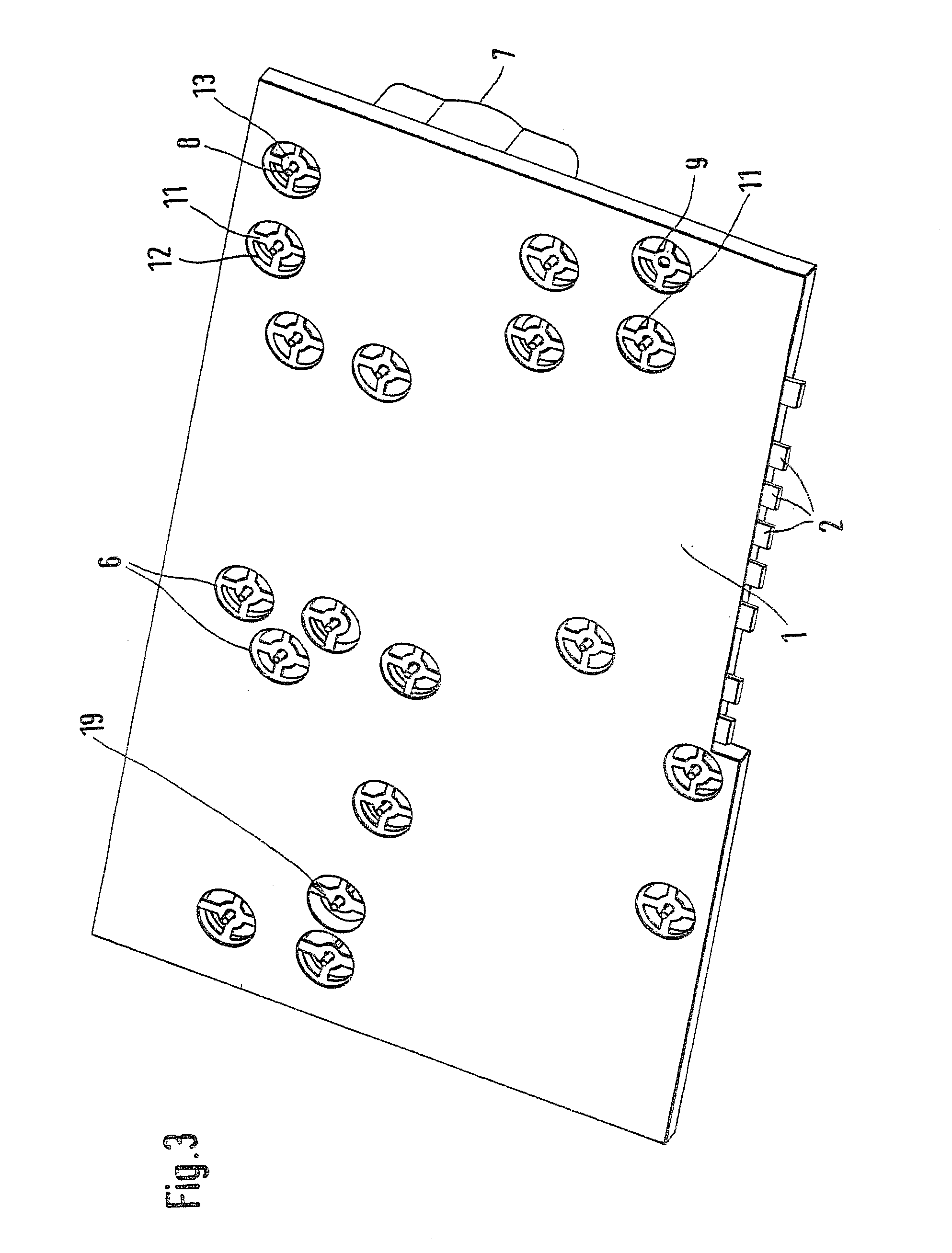
[0013]FIG. 1 shows a module frame 1, which includes a conductor structure that is formed from an essentially flat pressed screen and is composed of a plurality of metallic conductors 2. The conductor structure is produced by punching a thin sheet metal having a thickness of 1.2 mm, for example. By sheathing with a thermoplastic material, conductors 2 are embedded approximately in the center of an insulation sheathing 3, contact regions 9 of conductors 2 being uncovered by the plastic sheathing. Module frame 1 is designed in the form of a plate having a top side 1 and a bottom side 5. The cross-sectional diagram in FIG. 1 shows one of conductors 2.

[0014]A cutout 6 in the insulation sheathing 3 going from top side 4 to bottom side 5 permits access to a contact segment 10 of conductor 2, this contact segment being situated completely in cutout 3 and connected by only narrow connecting webs 11 to a segment 12 of conductor 2 situated on the inside wall of cutout 6. As shown in FIG. 2a, i...


PUM


Abstract

In a module frame for electronic components, having a conductor structure having a metallic conductor, at least one contact segment of a metallic conductor, the at least one contact segment of the metallic conductor uncovered by the insulation sheathing and conductively connected to a segment of the metallic conductor, the thermal conduction cross section of the at least one connecting web being designed to be so small that when the contact segment is intensely heated, the connecting web has a throttling effect on the heat flow to the segment of the conductor.

Description

FIELD OF THE INVENTION[0001]The present invention relates to a module frame for electronic components.BACKGROUND INFORMATION[0002]A module frame for electronic components is known, for example, from German Utility Model 296 22 806 U1 and includes a conductor structure formed by a pressed screen and a plurality of metallic conductors incorporated into an insulation sheathing. The conductor structure is usually punched out of sheet metal and then encased in plastic in an injection molding method. After punching, the individual conductors may at first remain joined by thin webs, which may then be separated before or even after sheathing with plastic through cutouts provided in the sheathing. Such module frames are used, for example, to join large heavy electric components or components operating at a high amperage to one another and to other electric components. To this end, contact regions of the module frame are provided, each including a contact segment of an electric conductor whic...

Claims


Application Information

Patent Timeline
Patent Type & Authority Patents(United States)
IPC IPC(8): H05K7/02H05K7/04H01L23/32H05K1/02H05K1/11H05K3/20H05K3/34H05K7/08
CPCH05K1/116H05K3/3447H05K1/0201H05K3/202H05K2201/0969H05K2201/0382H05K2201/0397H05K2201/062
Inventor SCHMID, ROLANDUHLAND, THOMASBECKBISSINGER, KAISCHINZEL, RALFHENNEL, UDO
Owner ROBERT BOSCH GMBH
Why Eureka
Try Eureka