Method and device for detecting three-dimensional information

Inactive Publication Date: 2006-03-21
NIPPON HOSO KYOKAI
View PDF5 Cites 61 Cited by
  • Summary
  • Abstract
  • Description
  • Claims
  • Application Information

AI Technical Summary

Benefits of technology

[0010]The image of the object can be acquired a plurality of times within the period of time corresponding to one frame of the video signal. In such a case, a signal-to-noise ratio (S/N) is improved by means of the storage effect of the image pick-up element, and the image pick-up intensity is enhanced.
[0011]A device for detecting three-dimensional information of the present invention comprises a projection section capable of projecting illumination light having given intensity on an object; an image pick-up section capable of acquiring an image of the object with a given image pick-up gain; and a signal processing section which calculates the distance between respective points of the object on the basis of intensity level information included in a video signal output from the image pick-up section. Either the given intensity or the image pick-up gain is changed with time, and the distance between respective points of the object can be detected at a speed at which the three-dime

Problems solved by technology

Therefore, under these methods, acquiring three-dimensional information pertaining to the object at a speed equal to the f

Method used


Image

  • Method and device for detecting three-dimensional information
  • Method and device for detecting three-dimensional information
  • Method and device for detecting three-dimensional information

Examples


first embodiment

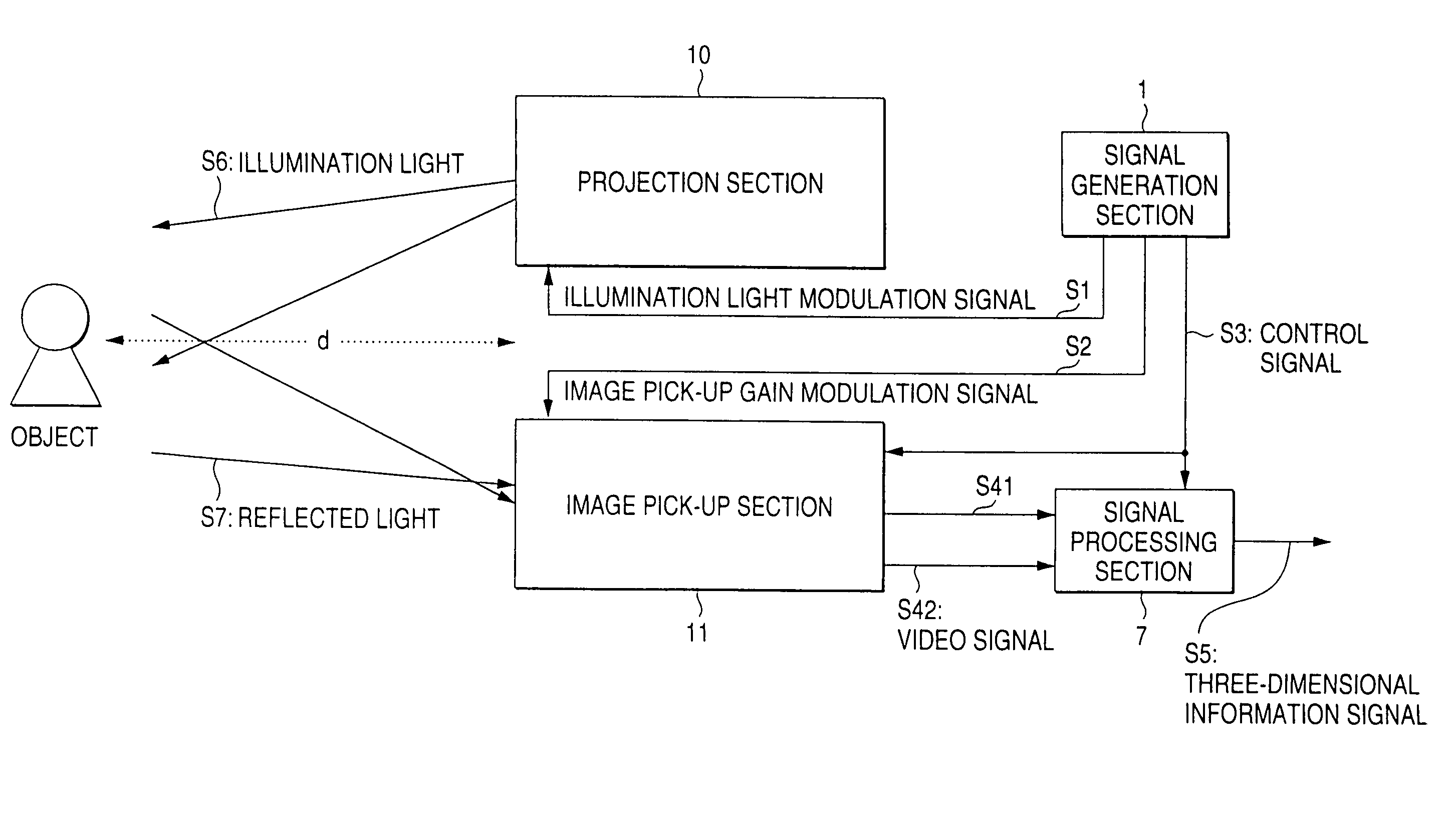
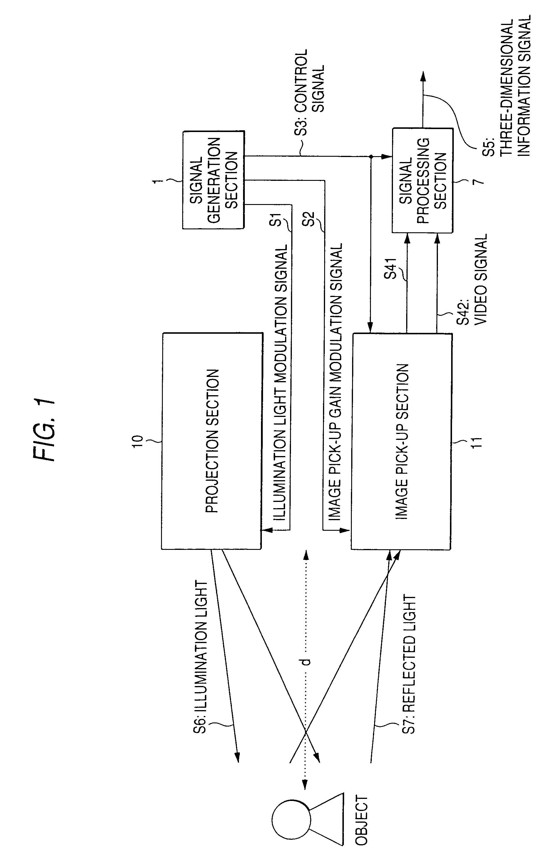
[0027]Various embodiments of the present invention will be described hereinbelow by reference to the accompanying drawings. FIG. 1 is a schematic diagram showing a three-dimensional information detecting device according to the present invention. The device comprises a projection section 10 capable of illuminating an object with illumination light S6 whose amplitude is modulated; an image pick-up section 11 which receives light S7 reflected from the object while changing an image pick-up gain with time and captures an optical image of the object; a signal processing section 7 for converting video signals S41 and S42 output from the image pick-up section 11 into a three-dimensional information signal S5; and a signal generation section 1 which produces an illumination light modulation signal S1, an image pick-up modulation signal S2, and a control signal S3. The specific configuration of these constituent elements will be described later.

[0028]The principle behind the three-dimension...

second embodiment

[0032]Referring to FIG. 4, a three-dimensional information detecting method according to the present invention will now be described. As shown in FIG. 4, the object is illuminated while the intensity of illumination light is modulated by employment of a triangular waveform. An optical image of reflected light is acquired twice; in other words, an optical image of reflected light whose intensity is I+ is acquired at time t=t0 for only a short period of time Δt (0(>0), and an optical image of reflected light whose intensity is I− is acquired at time t=to+T / 2 for only a short period of time Δt (0(>0). From Equations (1) and (6), we have R=I+⁢g0I-⁢g0=S⁡(t0-2⁢d / υ)I0-S⁡(t0-2⁢d / υ)(10)d=12⁢υ⁢{t0-I0S⁢(R1+R)}.(11)

Let the wavelength of illumination light modulated by a triangular waveform be defined as λ=νT; then from S=I0 / (T / 2), we have d=12⁢υ⁢⁢t0-λ4⁢(R1+R).(12)

Further, if t0 is set to a given value, distance “d” can be expressed as a relative distance with reference to a reference point dref...

third embodiment

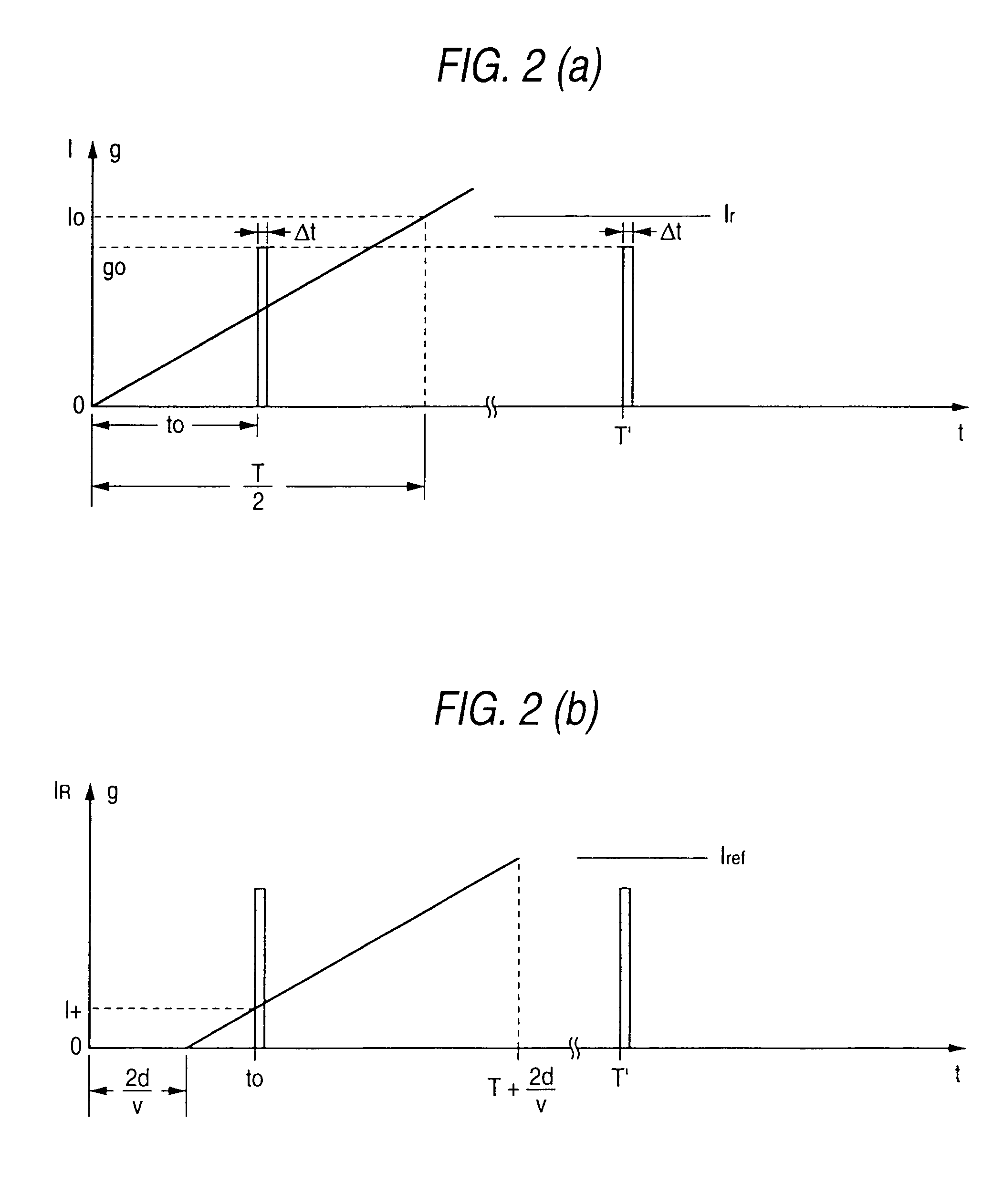
[0035]A three-dimensional information detecting method according to the present invention will be described by reference to FIGS. 5 and 6. As shown in FIG. 5A, illumination light is modulated such that an image pick-up gain “g” is linearly increased (i.e., g=Ut). Further, an object is exposed to light which illuminates like a pulse with intensity I=I0 for only a short period of time Δt (0 / T). The image pick-up gain g+ obtained when the light reflected from the object that is spaced only distance “d” from the three-dimensional information detecting device has returned to the image pick-up device becomes g+=U(t0+2d / v). The intensity IrOg+ of an image resulting from the reflected light being captured is expressed by Equation (14). Ir0⁢g+=σ(4⁢π⁢⁢d2)2⁢I0⁢U⁡(t0+2⁢d / υ)(14)

Further, in order to eliminate the dependency of term σ / (4π2)2, the object is illuminated for a short period of time Δt from time T′ while the image pick-up gain “g” is uniformly maintained at g=gr. At this time, luminous...


PUM


Abstract

An image of an object illuminated by illumination light having given intensity is formed as an optical image. The distance between respective points of the object is determined on the basis of a video which is obtained by acquiring the optical image with a given image pick-up gain. Here, either the intensity of the illumination light or the image pick-up gain is changed with time. The distribution of intensity of the image acquired by utilization of such intensity or image pick-up gain reflects a time lag between the time at which the illumination light is emitted from a light source and the time at which the light reflected from individual points of the object reaches an image pick-up device. The distribution of intensity includes information pertaining to the distance between the light source and the respective points of the object.

Description

FIELD OF THE INVENTION[0001]The present invention relates to a method and apparatus for detecting three-dimensional information pertaining to an object which can be applied to acquisition of a three-dimensional image, and more particularly, to a method and device which detects three-dimensional information pertaining to an object by two-dimensionally measuring the distance between points of the object at a speed at which the three-dimensional information can be followed in real time within a period relating to a frame of a video signal (hereinafter referred to simply as a “frame period”).PRIOR ART[0002]The following methods have conventionally been employed as techniques for measuring the distance between an object and an image acquisition device or three-dimensional information through use of light.[0003](1) As shown in FIG. 12, a pulse laser beam or a laser beam whose amplitude is modulated by a sinusoidal wave is radiated onto an object, and the distance between the object and th...

Claims


Application Information

Patent Timeline
IPC IPC(8): G06K9/00G01B11/00G01B11/24G01S17/89G06T1/00G06T7/00
CPCG01B11/24G01S17/89
Inventor NAKAMURA, HARUHITOAIDA, TAHITOKAWAKITA, MASAHIROIIZUKA, KEIGO
Owner NIPPON HOSO KYOKAI
Why Eureka
Try Eureka