Dispersion management with phase conjugation

a phase conjugation and dispersion management technology, applied in the field of optical transmission systems, can solve the problems of high bit rate systems, difficult management, severe limit performance, etc., and achieve the effect of minimizing the effects of nonlinearities

Inactive Publication Date: 2006-03-21
CORNING INC
View PDF24 Cites 11 Cited by
  • Summary
  • Abstract
  • Description
  • Claims
  • Application Information

AI Technical Summary

Benefits of technology

[0010]An optical transmission system is disclosed herein which includes optical fiber and transmits in a wavelength range bounded by a first wavelength and a second wavelength. Preferably, dispersion symmetry, and more preferably both dispersion and power symmetry, about the point of phase conjugation are implemented in order to minimize the effects of nonlinearities. The optical transmission system may also include a plurality of optical amplifiers that are positioned at one or more optical component sites to amplify the optical signal.

Problems solved by technology

However, because of non-linear effects in optical fiber, when the launched power is too great impairments are induced that can severely limit performance.
Dispersion is a physical property of optical fibers that can induce system penalties, and is most difficult to manage for high local dispersion fibers, long reach systems, and high bit rate systems.
In long-haul repeatered transmission systems using optical fibers, the interplay of the accumulation of large amounts of the chromatic dispersion and self-phase modulation (SPM), creates noise and distortion in the optical system.
However, such dispersion maps may be difficult to manage in an optically transparent network, for example because signals arriving at a switching node may have significantly different accumulated dispersion values, inhibiting the ease and accuracy of optical performance monitoring (OPM).
Another known technique proposed in the literature uses an optical phase conjugator, which inverts the phase induced by the non-linear interactions so that propagation forward from the location of the phase conjugator will undo the non-linear phase, but the technique does not utilize dispersion symmetry about the point of phase conjugation.

Method used


Image

  • Dispersion management with phase conjugation
  • Dispersion management with phase conjugation
  • Dispersion management with phase conjugation

Examples


Embodiment Construction

[0047]Preferably, the optical fibers in an optical transmission system are arranged to yield an average chromatic dispersion near zero for all the channels having wavelengths within the transmission wavelength range. Furthermore, the average dispersion of each channel should be substantially different from zero in each transmission span to reduce XPM effects, but should be periodically compensated to limit the accumulated dispersion. The dispersion compensation scheme should result in an increased number of channels over long distances for transmission applications which use a number of channels for transmission, such as wavelength division multiplexing (WDM). Significant cost savings can also be had by eliminating most of the dispersion compensation at the transmitter and receiver ends of the transmission system.

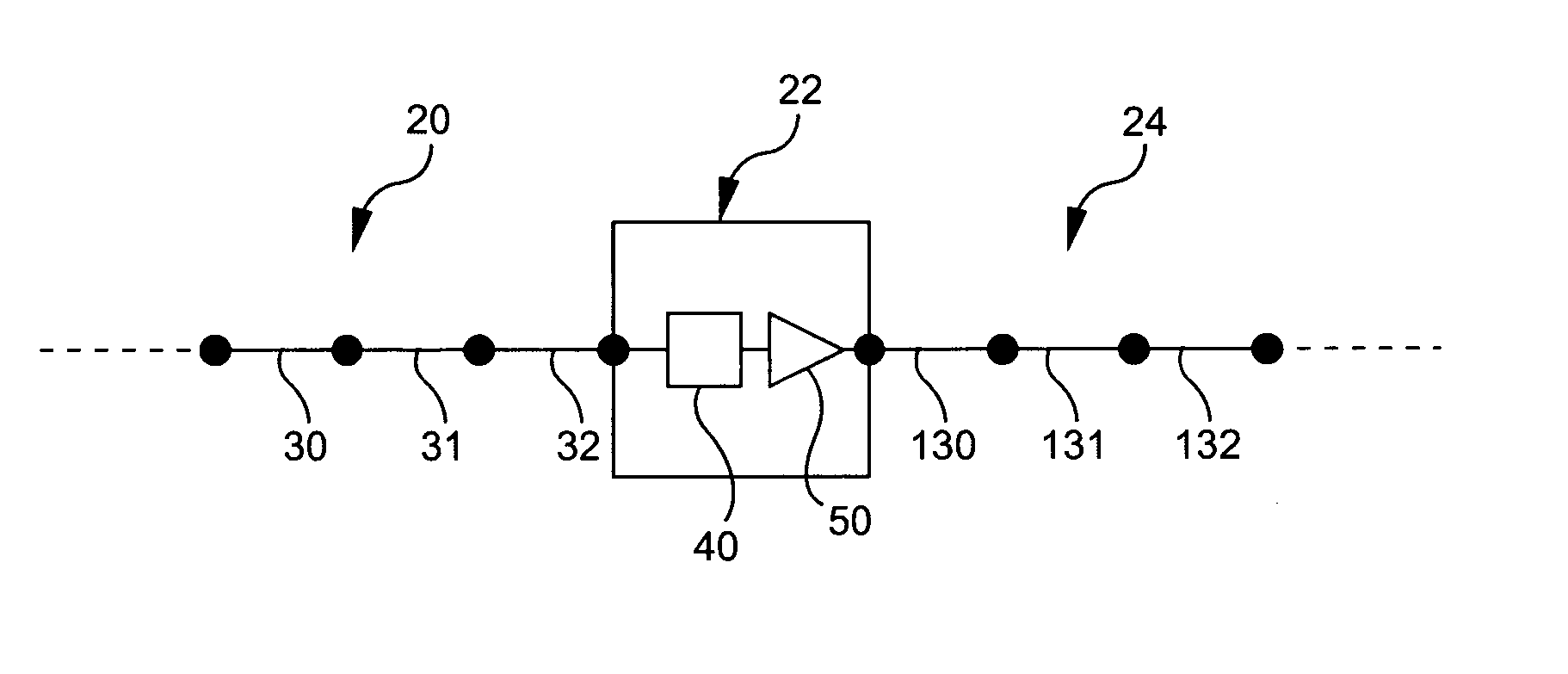
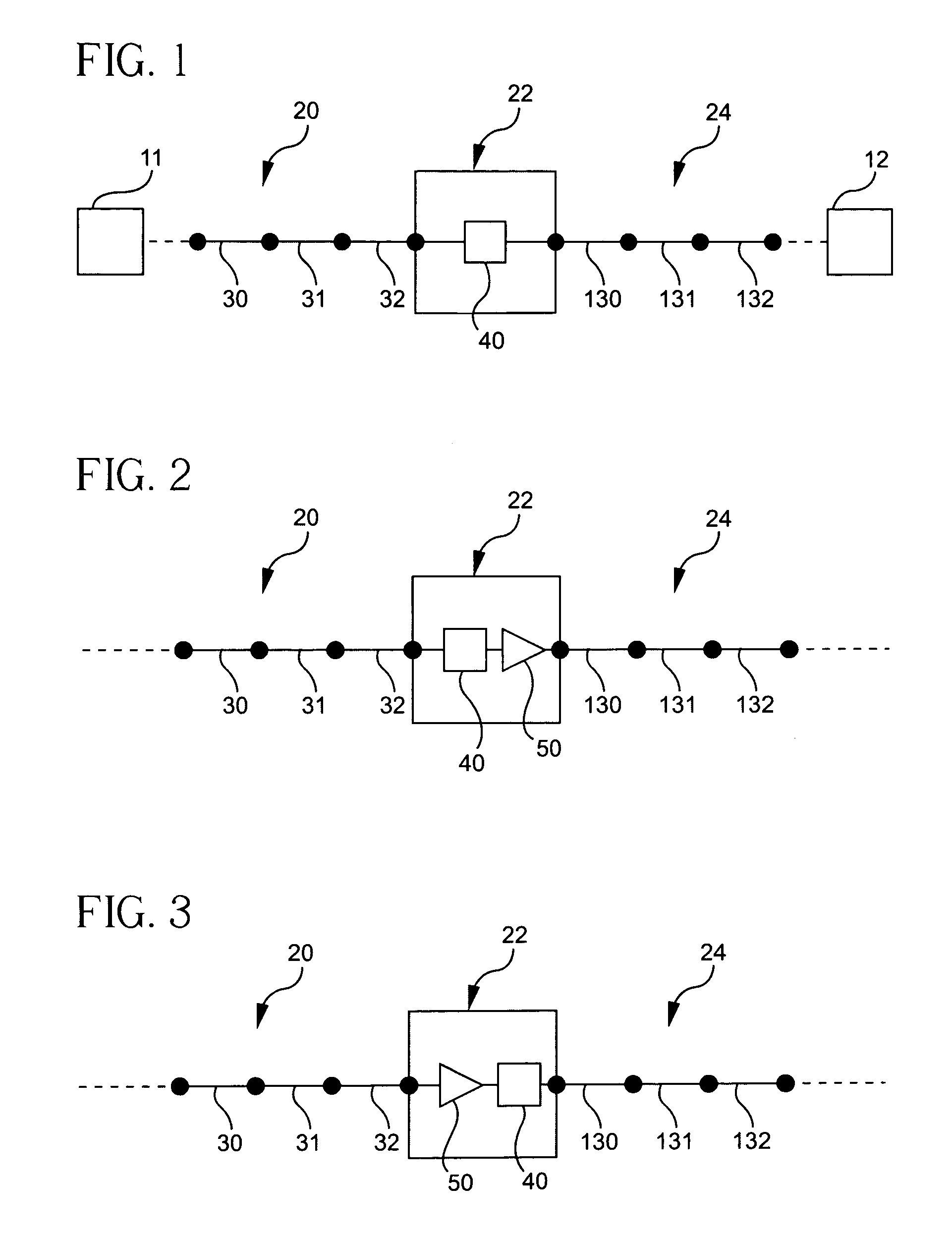
[0048]FIG. 1 is a schematic of an optical transmission system 10 as disclosed herein comprising a first dispersion managed span, or optical fiber line, 20, optically couple...


PUM


Abstract

An optical transmission system is provided. The system includes first and second lines of optical fiber, each line including first, second, and third optical fiber portions, and an optical phase conjugator optically coupling the first and second lines. The first and third optical fiber portions have a local dispersion of like sign to each other, and opposite to the sign of the second optical fiber portion.

Description

CROSS-REFERENCE TO RELATED APPLICATIONS[0001]This application claims the benefit of, and priority to, U.S. Provisional Patent Application No. 60 / 444,286 filed on Jan. 31, 2003.FIELD OF INVENTION[0002]This invention relates to an optical transmission system having dispersion managed optical fiber and optical phase conjugation. The transmission system and method are particularly applicable to high power, long distance transmission systems, including optically transparent systems.BACKGROUND OF THE INVENTION[0003]Since the development and widespread implementation of Erbium-doped fiber amplifiers (EDFAs) the development of optical fiber based communication systems has been a balance between various factors. The additive Gaussian noise induced by EDFAs drives systems to use higher launched powers to increase the signal to noise ratio (SNR) so that low bit error rates (BERs) can be maintained. However, because of non-linear effects in optical fiber, when the launched power is too great im...

Claims


Application Information

Patent Timeline
Patent Type & Authority Patents(United States)
IPC IPC(8): G02B6/02G02B6/26G02B6/34H04B10/18
CPCG02B6/29374H04B10/2531
Inventor DOWNIE, JOHN D.GROCHOCINSKI, JAMES M.KUMAR, SHIVA
Owner CORNING INC
Why Eureka
Try Eureka