Wireless system for measuring pressure and flow in tubes

a technology of pressure and flow in tubes and wireless systems, which is applied in the field of system for measuring the pressure and/or flow of a substance in a tube, can solve the problems of deleterious effects of response signals and inability to operate self-powered sensors that contain internal batteries at the momen

Active Publication Date: 2006-03-28
BH RES
View PDF8 Cites 41 Cited by
  • Summary
  • Abstract
  • Description
  • Claims
  • Application Information

AI Technical Summary

Benefits of technology

[0007]In a venal blood pressure application, the sensor preferably includes pressure amplification means comprising a lumen containing an incompressible fluid in a sealed lumen tube. A portion of the lumen tube has a deflecting diaphragm coupled to a deflecting spring member which operates with the sensor to affect an electrical characteristic of the response circuit. The deflecting diaphragm is more compliant and undergoes a larger deflection than the lumen tube in response to the generated pressure. The deflection of the deflecting diaphragm as compared to the deflection of the lumen tube is proportional to a ratio of a surface area of the lumen tube to the surface area of the deflecting diaphragm.

Problems solved by technology

As catheterization in humans ideally requires that the overall diameter of an implanted sensor be 2 millimeters (mm) or less, self-powered sensors that contain internal batteries are not practical at the present time.
However, such response signals may be deleteriously affected by interrogation signals generating signal artifacts including reflections from a variety of sources and other unwanted signal responses.

Method used


Image

  • Wireless system for measuring pressure and flow in tubes
  • Wireless system for measuring pressure and flow in tubes
  • Wireless system for measuring pressure and flow in tubes

Examples


Embodiment Construction

[0027]The following detailed description includes a description of the best mode or modes of the invention presently contemplated. Such description is not intended to be understood in a limiting sense, but to be an example of the invention presented solely for illustration thereof, and by reference to which in connection with the following description and the accompanying drawings one skilled in the art may be advised of the advantages and construction of the invention.

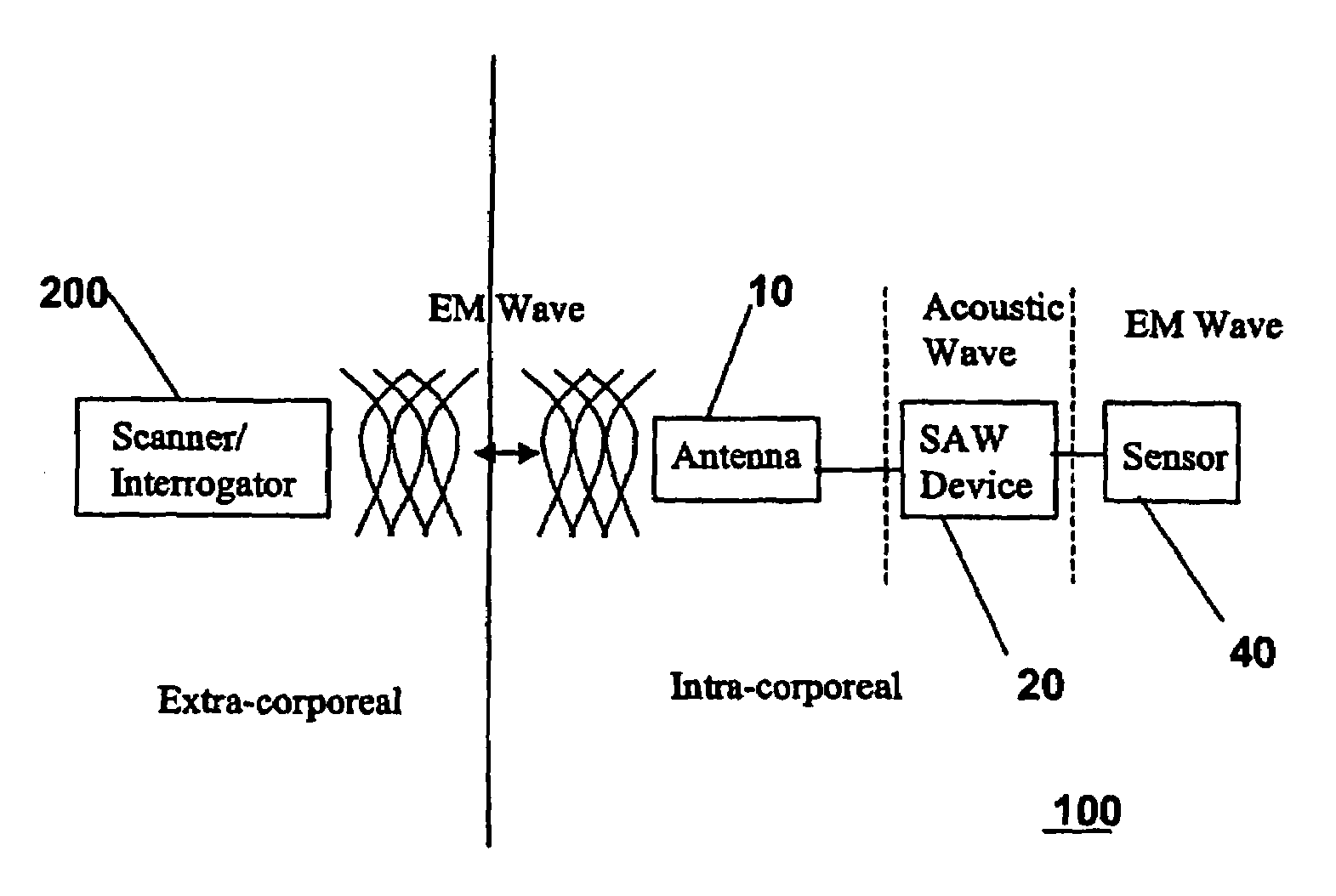
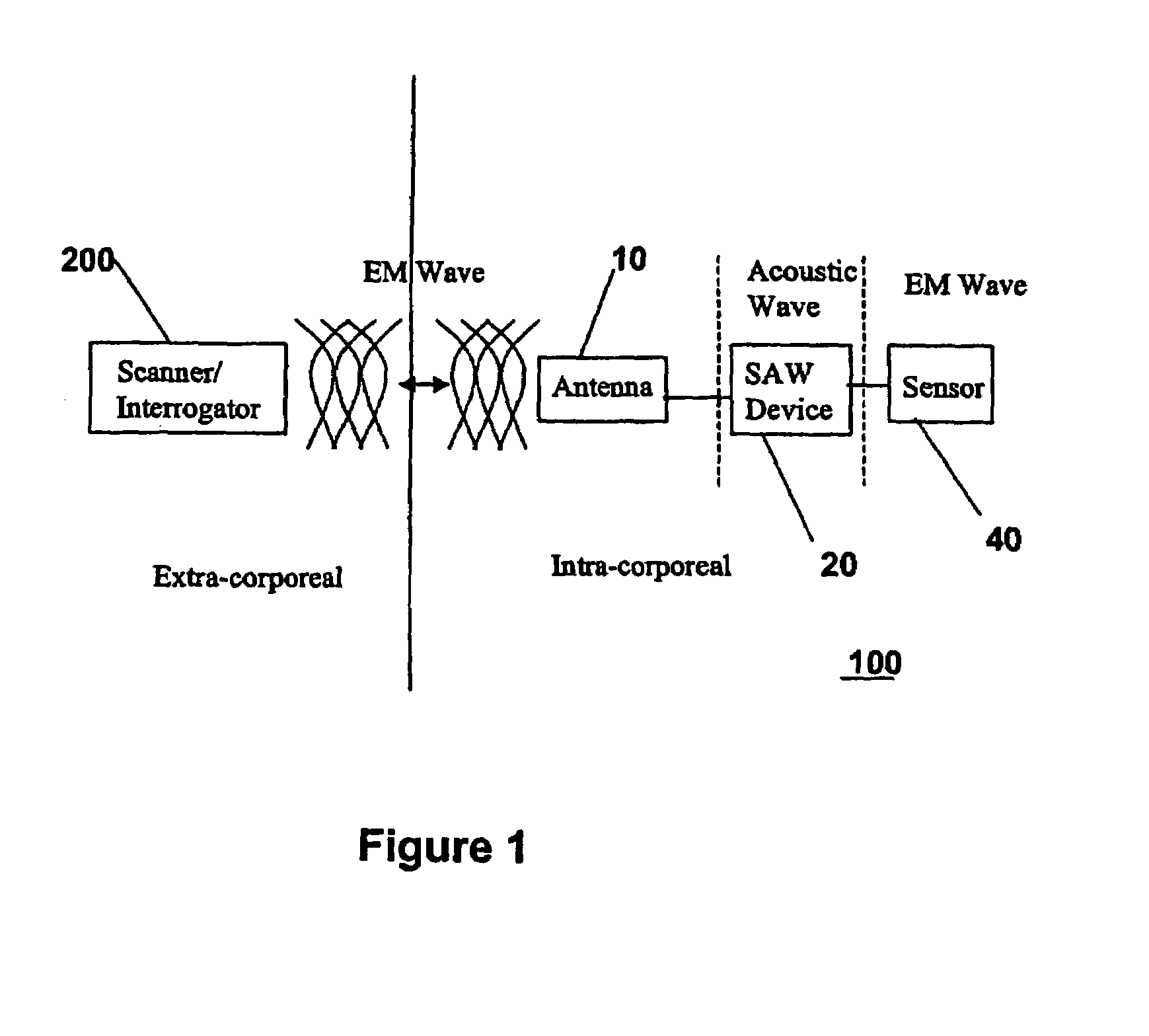
[0028]The present invention comprises a wireless system for measuring pressure and / or flow of a substance in a tube. The tube may include biological materials such as blood vessels, as well as industrial materials such as PVC (polyvinyl chloride) or stainless steel. The construction, geometry, and topology of the tube are inconsequential to the workings of the invention, the only tube requirement dictated by the system is that electromagnetic radiation can be introduced through the tube into the sensor component of th...


PUM


Abstract

A remote sensor (100) is remotely placed within a vessel containing a fluid in order to sense a pressure generated by the fluid. The sensor includes an antenna (10) for capturing an externally-generated interrogation signal and for transmitting a response signal, a response circuit (20, 30) coupled to the antenna (10) for receiving the interrogation signal and for generating the response signal, and a sensor element (40) coupled to the response circuit. One or more electrical characteristics of the response circuit (20, 30) change in relation to the sensed pressure, thereby determining measurable characteristics of the response signal. Importantly, the response circuit (20, 30) operates to delay the transmission of the response signal to a time separated from and following transmission of artifacts of the interrogation signal.

Description

[0001]This application is the National Stage of International Application No. PCT / US2003 / 031326, filed Oct. 2, 2003, which claims the benefit under 35 U.S.C. 119 (a–e) of U.S. Provisional Application 60 / 415,373 filed Oct. 2, 2002, which is herein incorporated by reference.FIELD OF THE INVENTION[0002]The present invention relates to a system for measuring of the pressure and / or flow of a substance in a tube. More particularly, the present invention relates to a wireless system including an intra-corporeal, externally-powered sensor for measuring of the pressure and / or flow of a substance in a tube.BACKGROUND OF THE INVENTION[0003]In International Application No. PCT / US02 / 09543 entitled “Wireless System for Measuring Distension in Flexible Tubes” to Kain (“Kain I”), which is hereby incorporated by reference, methods for measuring blood parameters in living beings are described. As is disclosed in Kain I, it is known in the prior art to measure blood pressure by the implantation of a m...

Claims


Application Information

Patent Timeline
Patent Type & Authority Patents(United States)
IPC IPC(8): B60C23/02
CPCA61B5/0215A61B5/076G01L19/086A61B2562/02A61B2560/0219
Inventor KAIN, ARON ZEV
Owner BH RES
Why Eureka
Try Eureka