Power supply with disconnect fuse

a power supply and fuse technology, applied in the field of power supply, can solve the problems of total feed voltage burst, inability to disconnect the conventional fuses for the individual outputs, and loss of data in the central control unit supplied by the feed voltage, etc., to achieve expedient and economical triggering, reduce power dissipation, and simplify the effect of monitoring unit triggering

Inactive Publication Date: 2007-11-08
SIEMENS AG
View PDF12 Cites 7 Cited by
  • Summary
  • Abstract
  • Description
  • Claims
  • Application Information

AI Technical Summary

Benefits of technology

[0017] In an expedient variant, provision is made for the monitoring unit to be set up to keep the auxiliary semiconductor switch at least substantially disconnected during normal operation, but to switch it on in the event of an overload as the main semiconductor switch is simultaneously disconnected. In this way it is possible to affect the characteristic of the transition from the main switch to the auxiliary switch by appropriate design of the monitoring unit.
[0018] It is especially advantageous if a ballast resistor is connected in series with the auxiliary semiconductor switch. In this way, the majority of the heat is dissipated in the ballast resistor and the auxiliary semiconductor switch can be dimensioned for a lower power dissipation and therefore be cheaper. In the process it is advisable if the given short circuit current of the branch is determined essentially by the ballast resistor and the feed voltage so that R1A≈Us / IK1.
[0019] In practice, it is expedient and economical if the semiconductor switches are of the FET type. In this manner, the triggering by the monitoring unit may be simplified. In so doing an especially simple solution in terms of circuitry is achieved if the semiconductor switches are of the self-locking FET type, the gate of the main semiconductor switch being connected to the source and triggered by an output of the monitoring unit via a Zener diode, and the gate of the auxiliary semiconductor switch being directly triggered by the same output. A ballast resistor, which is formed as a composite carbon resistor, is especially well-suited to absorb the power impulse that occurs when there is a disconnection.

Problems solved by technology

Short circuits or overloads in partial areas of a control system, for example, in the output peripherals, can easily result in a complete, albeit usually only brief, failure of the feed voltage of the control system, which often leads to a loss of data in the central control units that are supplied by the feed voltage.
The increasing use of switched mode power supplies highlights this problem since, because of the sensitive electronics, the internal control circuits limit the output current to values only slightly higher than the nominal current.
There exists in particular the problem that conventional fuses for the individual outputs are unable to disconnect in a sufficiently brief period of time.
However, the switched mode power supplies cannot supply this in addition to the remaining load, so that the total feed voltage bursts in—even before a fuse triggers and the faulty output or branch is cleared.
Then, if the limit current is exceeded, the transistor—together with the monitoring circuit—begins to hold the output flow constant in order not to overload the feed source too much and thus provoke a crash of the entire system.
Because the transistor, for example of the MOSFET type, has already been heated up during normal operation, the absorption of the additional power loss in the limit state is problematic.
In this short time, the heat cannot at all be passed on to a heat sink and therefore must be absorbed by the transistor chip.
In order to prevent destruction of the switching transistor before disconnection, transistors having very large chip surfaces must therefore be used, which results in high costs.
Cycled switching transistors are always present in this case; however, the set of problems involving a disconnect fuse, which in principle is only switched on or off, is not present.

Method used


Image

  • Power supply with disconnect fuse
  • Power supply with disconnect fuse
  • Power supply with disconnect fuse

Examples


Embodiment Construction

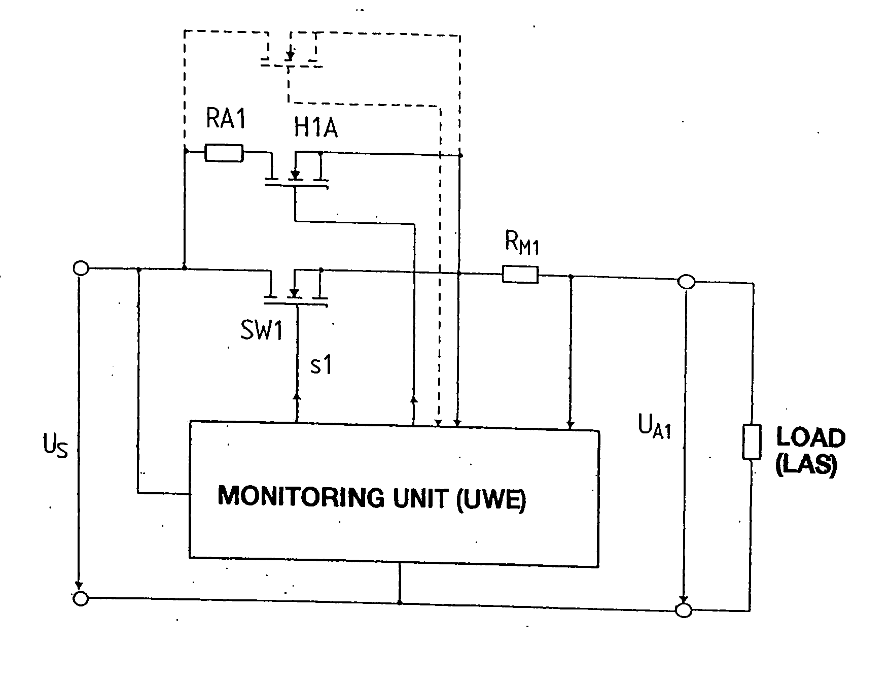
[0024] According to FIG. 2, which concerns only one branch of a circuit according to FIG. 1, load LAS is connected across a semiconductor switch SW1, in this case a self-locking n-channel IGFET, to feed voltage Us. As already explained with respect to FIG. 1, a monitoring unit UWE, by corresponding signal to the gate of switch SW1, provides for the opening of the latter if, for example, the current measured using resistor RM1 exceeds a pre-defined maximum value. Variants of the disconnection conditions are possible, for example, a disconnection as a function of the output voltage or input voltage and combinations of such disconnection conditions.

[0025] The basic function of such an electronic fuse is to prevent a current of any given size from being able to flow through a branch. In reality, this is the typical function of a circuit breaker, with the additional characteristic that an operating state of the current limitation is still picked up before complete interruption of the cu...


PUM


Abstract

A power supply in which a feed voltage (Us) is guided through at least one longitudinal branch to at least one output, the at least one branch having a disconnect fuse formed as a controlled semiconductor switch (SW1) and a monitoring unit (UWE) being set up to supply a disconnect signal (s1) to the semiconductor switch when there are changes in voltage or current beyond pre-definable tolerances, in which at least one auxiliary semiconductor switch (H1A), likewise triggered by the monitoring unit (UWE), is connected in parallel to the semiconductor switch (SW1) and in the event of an overload absorbs a substantial portion of the overload current in the branch.

Description

CROSS-REFERENCE TO RELATED APPLICATION [0001] This application is a Divisional application of U.S. patent application Ser. No. 10 / 678,566 filed Oct. 3, 2003 which in turn claims the benefit of Austrian Patent Application Serial No. A 560 / 2001, filed Apr. 6, 2001 and PCT Patent Application Serial No. PCT / AT 02 / 00079, filed Mar. 11, 2002.FIELD OF THE INVENTION [0002] The invention relates to a power supply in which a feed voltage is routed via at least one series arm to at least one output, the at least one arm having a disconnect fuse formed as a controlled semiconductor switch and a monitoring unit being set up to send a disconnect signal to the semiconductor switch in the event of changes in voltages or currents past given tolerance values. BACKGROUND OF THE INVENTION [0003] In industrial systems and in automated systems, it is of particular significance that the feed voltages of the individual loads or load groups are supplied according to special safety criteria. In particular, i...

Claims


Application Information

Patent Timeline
Patent Type & Authority Applications(United States)
IPC IPC(8): H02H3/08H02H3/05H02H3/087H02J1/14
CPCH02H3/05H02J1/14H02H3/087H02H9/001H03K17/0822H02H7/222
Inventor HALLAK, JALALSCHWEIGERT, HARALD
Owner SIEMENS AG
Why Eureka
Try Eureka