Engine controller

a technology of engine controller and camshaft, which is applied in the direction of electric control, ignition automatic control, speed sensing governor, etc., can solve the problems of increasing the size of the cylinder head, the inability to use cam sensors often, and the cost of cam sensors for detecting the phase state of the camsha

Inactive Publication Date: 2006-03-28
YAMAHA MOTOR CO LTD
View PDF19 Cites 15 Cited by
  • Summary
  • Abstract
  • Description
  • Claims
  • Application Information

AI Technical Summary

Benefits of technology

[0014]The invention is further characterized in that, the idling detecting means sets the predetermined value of the intake pressure for detecting the idling state to be larger as the atmospheric pressure detected by the atmospheric pressure detecting means is higher.

Problems solved by technology

However, a so-called cam sensor for detecting the phase state of a camshaft is expensive.
In a two-wheeled vehicle, particularly, a cam sensor cannot be often employed because of a problem in that the size of a cylinder head is increased.
Actually, however, a specific ignition timing controlling technique for, in, for example, a state immediately after start of rotation of an engine, adequately controlling the unstable engine speed in an idling state is not proposed.

Method used


Image

  • Engine controller
  • Engine controller
  • Engine controller

Examples


Embodiment Construction

[0041]Hereinafter, embodiments of the invention will be described.

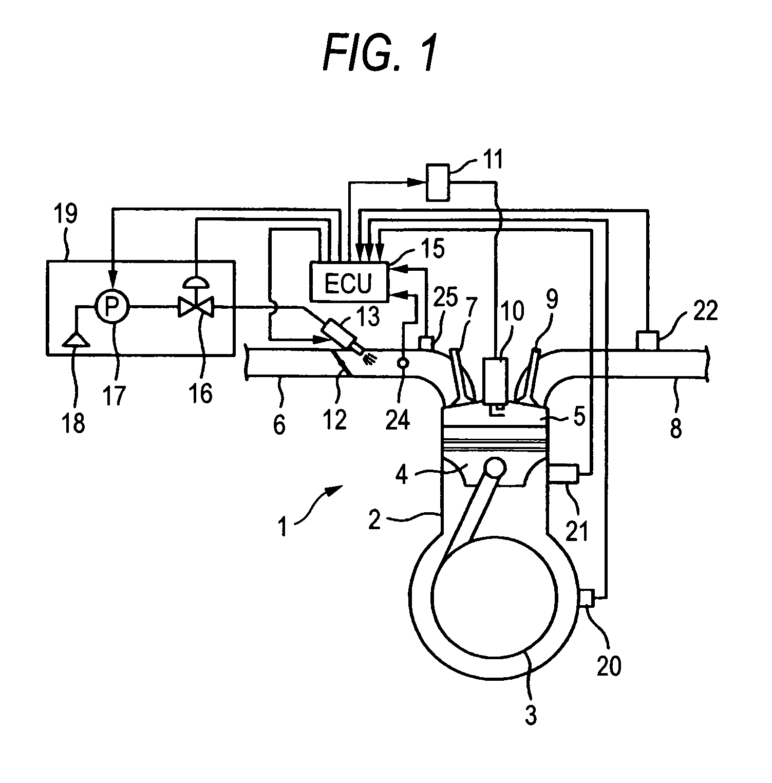
[0042]FIG. 1 is a diagram showing the configuration of, for example, an engine for a motorcycle and an example of a control apparatus for the engine. The engine 1 is a single-cylinder four-cycle engine of a relatively small displacement, and comprises a cylinder body 2, a crankshaft 3, a piston 4, a combustion chamber 5, an intake pipe (intake passage) 6, an intake valve 7, an exhaust pipe 8, an exhaust valve 9, a spark plug 10, and an ignition coil 11. A throttle valve 12 which is opened or closed in accordance with the degree of an accelerator operation is disposed in the intake pipe 6, and an injector 13 serving as a fuel injection apparatus is disposed in the intake pipe 6 downstream from the throttle valve 12. The injector 13 is connected to a filter 18 which is disposed in a fuel tank 19, a fuel pump 17, and a pressure control valve 16. A centrifugal clutch is interposed between the engine 1 and a transmission.

[...


PUM


Abstract

An unstable idling state immediately after engine start is stabilized. The difference between a target idling engine speed corresponding to the cooling water temperature and an actual engine speed is integrated. The ignition timing is changed toward advance or retard while using a value obtained by multiplying the integration value of the engine speed difference with a gain, as an ignition timing changing amount. Immediately after engine start, the gain is made relatively large to rapidly increase engine speed. When the engine speed approaches the target engine speed, the gain is set to a smaller usual gain, and, in a change to the same advancing or retarding side, a change to an ignition timing in the same side is suppressed using a smaller advancing or retarding gain. In a throttle-off state, an ignition timing corresponding to the cooling water temperature is set to rapidly reduce engine speed.

Description

TECHNICAL FIELD[0001]The present invention relates to an engine controller which controls an engine, and more particularly to an apparatus suitable for controlling an engine having a fuel injection apparatus which injects fuel.BACKGROUND ART[0002]Recently, as a fuel injection apparatus which is called an injector is more widely used, the fuel injection timing, the amount of injected fuel, i.e., the air-fuel ratio, and the like can be more easily controlled, so that a higher output power, smaller fuel consumption, exhaust gas purification, and the like can be enhanced. With respect to the fuel injection timing, particularly, the state of an intake valve in a strict sense, or the phase state of a camshaft in a usual sense is detected, and fuel is usually injected in accordance with the detected state. However, a so-called cam sensor for detecting the phase state of a camshaft is expensive. In a two-wheeled vehicle, particularly, a cam sensor cannot be often employed because of a probl...

Claims


Application Information

Patent Timeline
Patent Type & Authority Patents(United States)
IPC IPC(8): F02D41/16F02D31/00F02D41/06F02D41/08F02D41/18F02P5/15F02P9/00
CPCF02D31/001F02D41/086F02D41/1402F02D41/182F02P5/1506F02P5/1508F02P9/005F02D41/064Y02T10/46F02D41/1454F02D2041/1409F02D2041/1422F02D2200/0402F02D2200/0406F02D2200/0414Y02T10/40
Inventor SAWADA, YUICHIROHASEGAWA, HITOSHITAKAHASHI, MICHIYASU
Owner YAMAHA MOTOR CO LTD
Why Eureka
Try Eureka