Injection device for injecting fuel

Active Publication Date: 2006-03-28
VITESCO TECH GMBH
View PDF11 Cites 11 Cited by
  • Summary
  • Abstract
  • Description
  • Claims
  • Application Information

AI Technical Summary

Benefits of technology

[0005]It is therefore the object of the present invention to provide an injection device with a micro-bore nozzle,

Problems solved by technology

In the case of a small needle lift, for example for a preliminary or subsequent injection, with a micro-bore nozzle poor uniform distribution of fuel or a poor jet pattern may result from the small flow cross-section between the needle and the nozzle body.
This results in deterioration of combustion processes in the combustion chamber and therefore to poor levels of exhaust g

Method used


Image

  • Injection device for injecting fuel
  • Injection device for injecting fuel
  • Injection device for injecting fuel

Examples


Example

[0024]A first embodiment of the present invention is described below with reference to FIGS. 1 and 2.

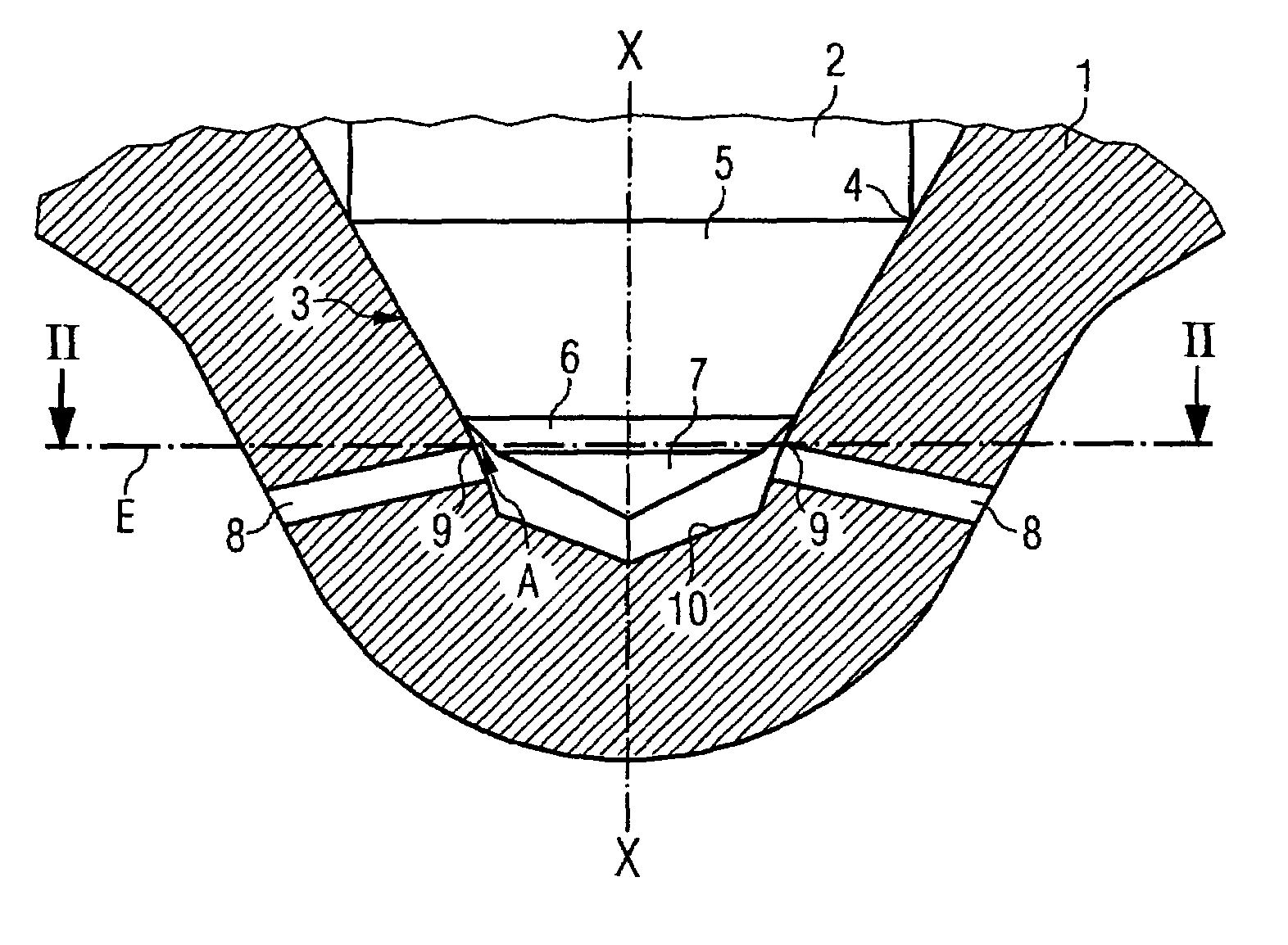
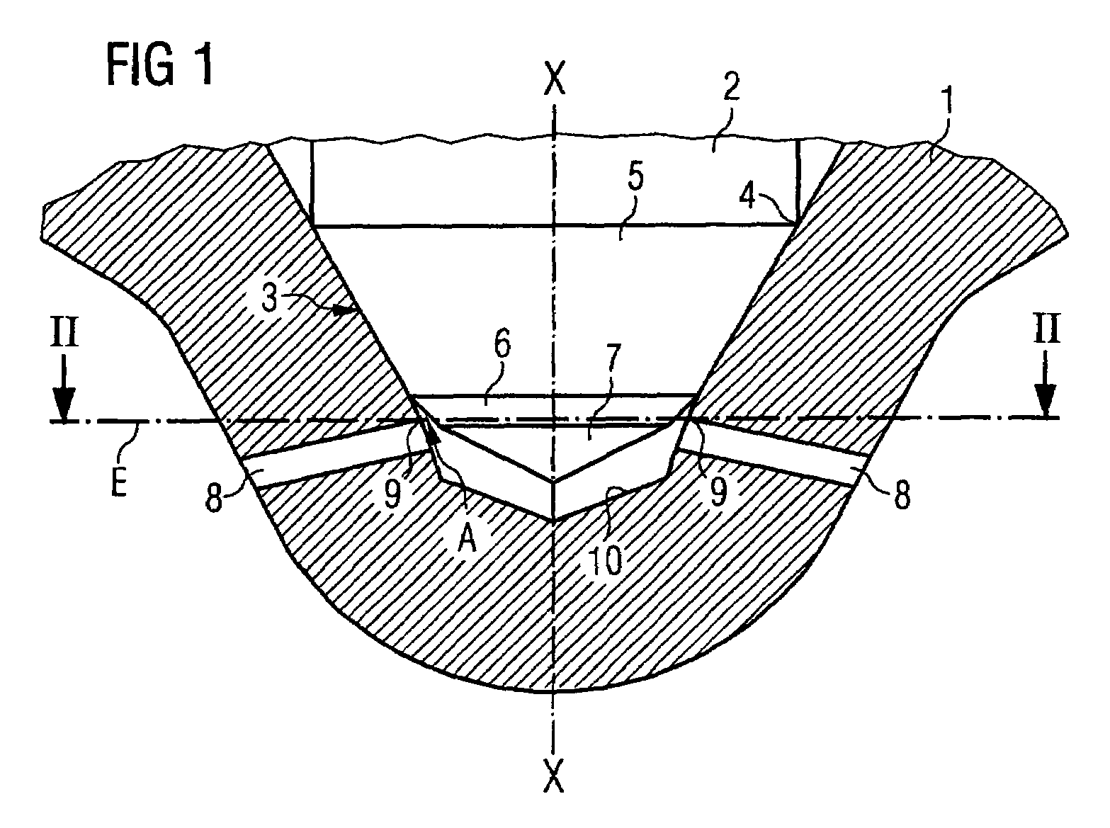
[0025]As shown in FIG. 1, in the known manner the injection device comprises a nozzle needle 2 arranged in a nozzle body 1. The nozzle needle 2 rests at a seal fit 4 on the nozzle body 1 and releases or seals the seal fit, for example by activation by means of a piezo actuator, in the known manner by movement along the longitudinal axis X—X of the nozzle needle 2, to start or end an injection. The nozzle needle 2 comprises an essentially conically shaped tip 3. In the present embodiment the tip 3 is formed by a first conical area 5, a second conical area 6 and a third conical area 7. The conical areas 5, 6, 7 here are configured so that they are each at a different angle to the longitudinal axis X—X. More precisely the first conical area 5 is at the most acute angle in respect of the axis X—X and the third conical area 7 at the end of the tip 3 is at the most obtuse angle in respect ...

Example

[0029]An injection device according to a second embodiment of the present invention is described below with reference to FIG. 3. Identical or functionally identical parts are referred to here with the same references as in the first embodiment.

[0030]Unlike the first embodiment, with the second embodiment the tip 3 of the nozzle needle in the area facing the injection hole 8 is formed by an approximately parabolic, tapering area 11. This tapering area 11 of the tip 3 is configured here so that an area A with a minimum cross-section of approx. 0.200 mm2 results between the uppermost edge point 9 of the injection hole 8 and the tapering area 11.

[0031]This means that even when the nozzle needle is closed there is an adequate distance between the tip of the nozzle needle and the injection holes 8, so that improved injection and therefore also in particular an improved exhaust gas response on the part of the engine can be achieved. The tapering area can also be produced by grinding for ex...


PUM


Abstract

An injection device for injecting fuel comprises a nozzle needle (2), which is arranged in a nozzle body (1), and a micro-bore (10) formed in the nozzle body (1), in which at least one injection hole (8) is configured. Here one tip (3) of the nozzle needle (2) projects into the micro-bore (10) in such a way that the tip (3) is arranged at the level of the injection holes (8) in the axial direction (X—X) of the nozzle needle, with recesses being formed in the tip at the tip (3) of the nozzle needle (2) level with the injection holes (8), in order to ensure a minimum distance between the tip (3) and the injection holes (8).

Description

PRIORITY[0001]This application claims foreign priority of the German application DE 10246693.9 filed on Oct. 7, 2002.TECHNICAL FIELD[0002]The present invention relates to an injection device for injecting fuel, in particular in a combustion chamber of an internal combustion engine.BACKGROUND OF THE INVENTION[0003]Various embodiments of injection devices for injecting fuel into a combustion chamber of an internal combustion engine are known from the prior art, in particular in conjunction with storage-type injection systems, such as for example common rail systems for injecting diesel fuel into a combustion chamber of an engine. Such injection devices comprise a nozzle needle guided in a nozzle body, with a seal fit being created at one tip of the nozzle needle between the nozzle needle and the nozzle body. Below the seal fit in the exit direction a number of injection holes are generally arranged, which branch off from a bore on the nozzle body and through which the fuel is injected...

Claims


Application Information

Patent Timeline
IPC IPC(8): B05B1/30F02M61/18
CPCF02M61/1873
Inventor KRUGER, GRITKULL, EBERHARDLOBBERING, FERDINANDSCHINDLATZ, JURGENSENGHAAS, CLEMENS
Owner VITESCO TECH GMBH
Why Eureka
Try Eureka