Method for producing a connection interface in a filter element and device for producing the same

Inactive Publication Date: 2006-03-28
HYDAC FILTERTECHNIK GMBH
View PDF11 Cites 28 Cited by
  • Summary
  • Abstract
  • Description
  • Claims
  • Application Information

AI Technical Summary

Benefits of technology

[0009]Objects of the present invention are to provide a process for production of a tubular filter element which ensures connection of the filter mat ends while avoiding use of adhesives, which reduces the volume of material used in manufacturing and accordingly lowers the production costs, and which produces a reliably operating connection interfaces, even under the highest stresses.
[0011]In addition to relief of pressure on the embossed weld seam by the smooth weld seam, however, the embossed weld seam is also advantageous for production of the smooth weld seam, since the free filter mat ends are precisely adjusted in relation to each other during the embossing process and so are connected to each other free of displacement. This feature also promotes improvement in the quality of the smooth weld seam, which is produced simultaneously with the embossed weld seam, and accordingly, is marked by very high production quality. Simultaneous application of smooth weld seam and embossed weld seam thus yields a synergistic effect, such that the two intrinsically different weld seam areas exert a favorable effect on the other weld seam area.
[0012]The device for performing the present invention employs an ultrasonic welding device for production of the filter element. Such connection process is especially favorable with respect to energy needed for the filter mat ends.
[0013]In one preferred embodiment of the process of the present invention, for connection of the filter mat ends, a connecting strip in the form of a clip is used which is composed of a thermoplastic and holds the filter mat ends together during the welding process after the clip has been positioned on these ends. This connecting clip is advantageous, especially if the filter mat itself has only a small amount of plastic materials which may be joined together by thermal means. In addition, placing a connecting strip subsequently to be welded in position may be advantageous if the outermost filter mat layer comprises a metal support wire fabric.

Problems solved by technology

However, despite the steps provided for this purpose, the filter mat ends may be forced together during introduction of the configuration into a welding device, with the result that the quality of the weld seam to be applied may be appreciably lowered.
Consequently, the filter element may subsequently fail in the area of the welded seam points when in use.
This is true in particular of filter elements subjected to high stresses when the weld seam connection is separated, something which may result both in failure of the filter element and in failure of an entire hydraulic assembly in which that filter element has been installed.
With this solution, it is not possible to seal or weld tubular filter elements and their filter materials by means of ultrasound.
Reliability in operation, even under high load, cannot be achieved with the solution disclosed.
The wide gap impairs the sealing efficiency, and may be a factor if the embossed weld seam as produced is not entirely clean and is forced apart so that passages may be formed for undesirable escape of fluid.
Introduction of material stresses into the embossed weld seam through the additionally widening gap occurs in the transitional area between pleating and embossed weld seam, so that the respective weld seam undergoes introduction of high punctate or linear forces to such an extent that failure may also occur, particularly if the filter element is subjected to alternating pressure stresses during operation.

Method used


Image

  • Method for producing a connection interface in a filter element and device for producing the same
  • Method for producing a connection interface in a filter element and device for producing the same
  • Method for producing a connection interface in a filter element and device for producing the same

Examples


Embodiment Construction

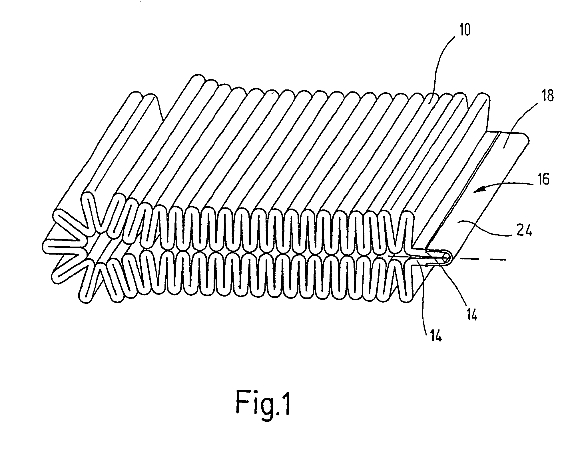
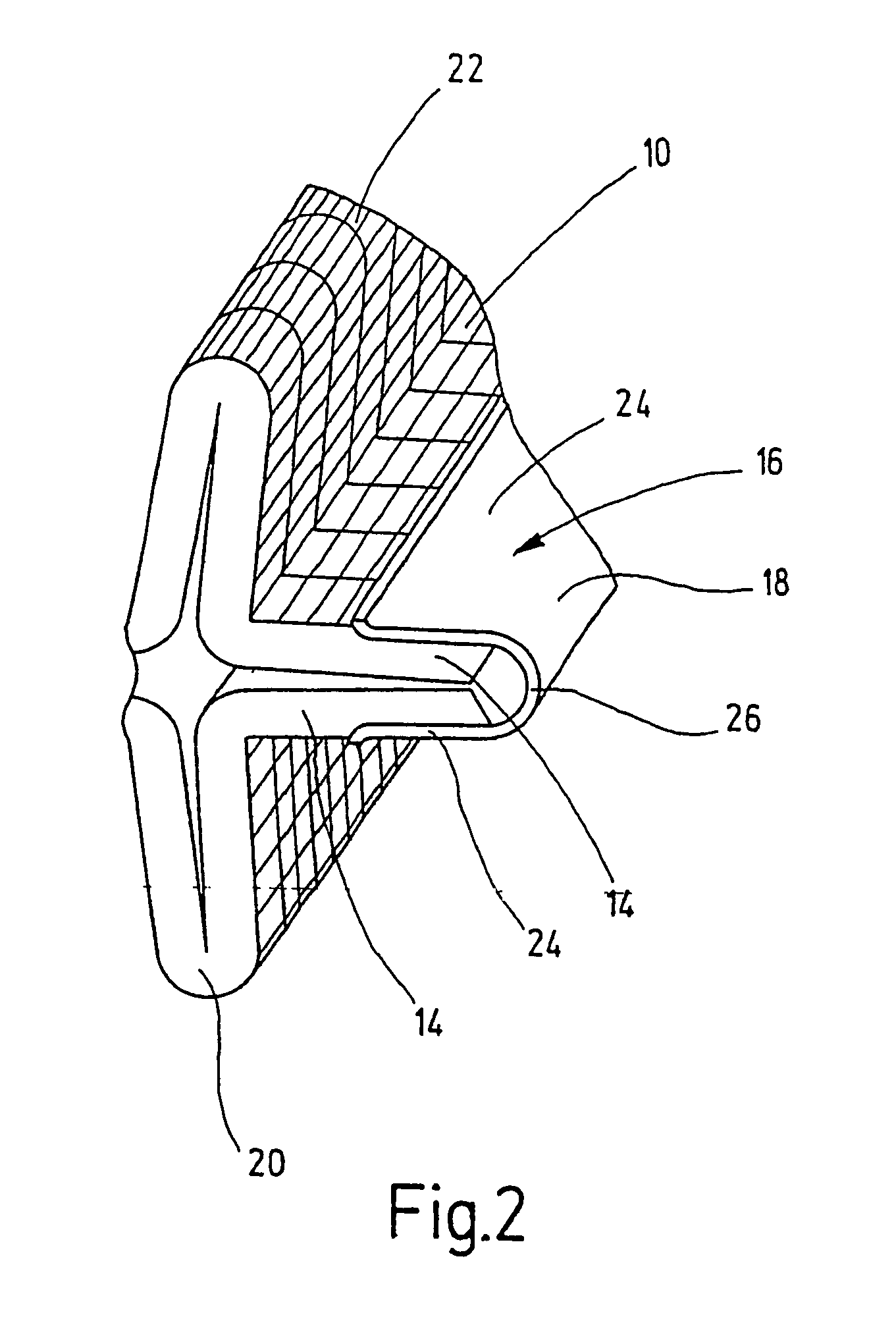
[0025]A front view of the tubular filter element is presented in FIG. 3. The filter element is used for filtration of fluids and has a filter mat 10 folded in zigzag form or pleated. Although not shown in detail, the filter mat 10 is made of multiple layers and may have the following laminate structure, for example, from the exterior inward:[0026]1. Metal wire fabric or plastic fabric or plastic screen with reticular structure;[0027]2. Polyester formed fabric;[0028]3. Glass fiber mat or meltblown formed fabric;[0029]4. Glass fiber mat or meltblown formed fabric;[0030]5. Paper fabric or polyester formed fabric;[0031]6. Composite special steel-polyester fabric; and[0032]7. Metal wire fabric or plastic fabric or plastic screen with reticular structure.

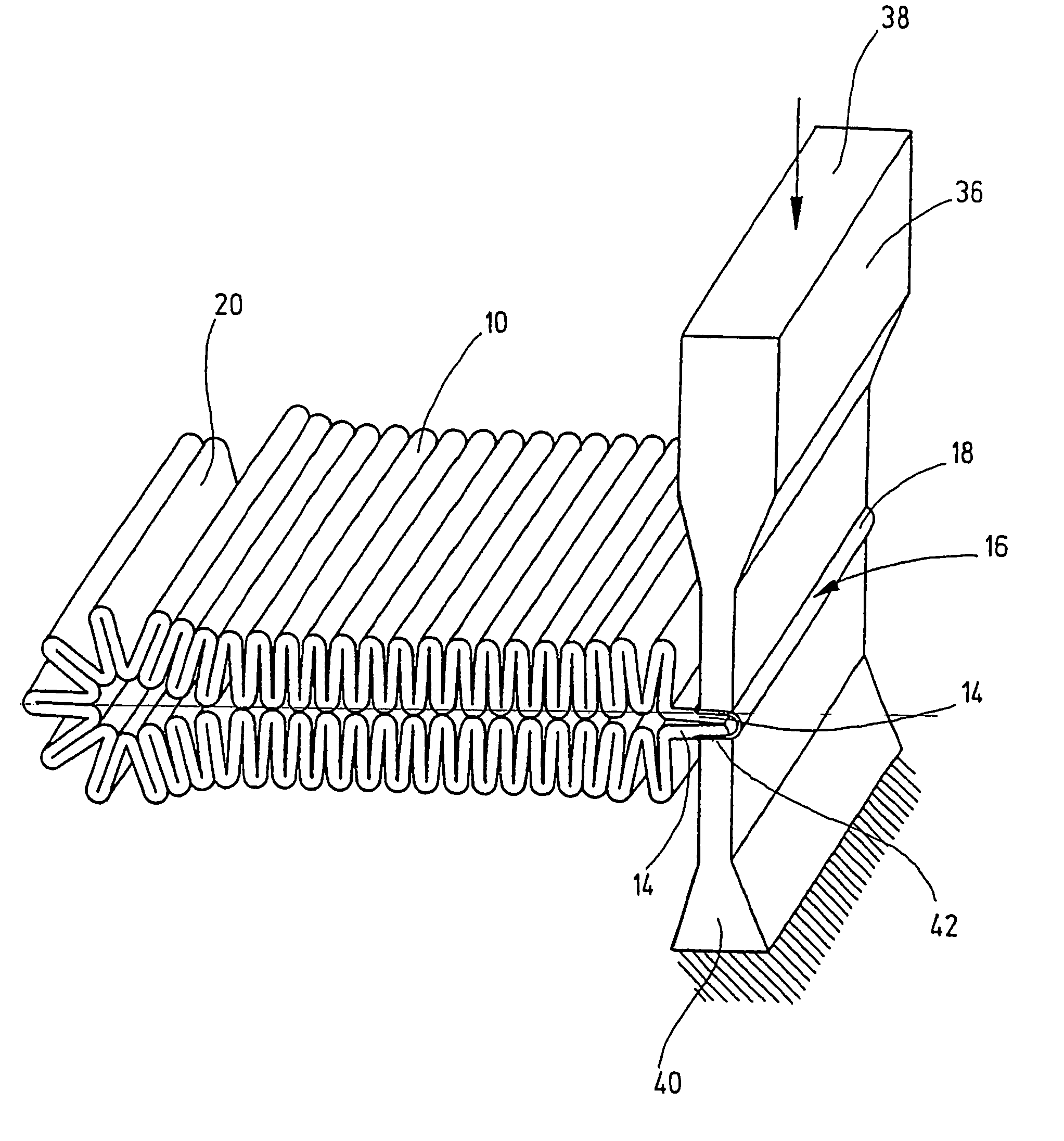
[0033]To support the filter mat 10, the interior of the filter element has a metal support tube provided with fluid passages (not shown). The two opposite ends 14 of the filter mat 10 extend at an acute angle to each other. Their length i...


PUM

PropertyMeasurementUnit
Areaaaaaaaaaaa
Circumferenceaaaaaaaaaa
Plasticityaaaaaaaaaa

Abstract

A method produces a connection interface in a tubular filter element for filtering liquids, including a filter mat (10). The opposite ends (14) of the filter mat are interconnected in a connection position by a planar weld seam (28) provided with an embossed strip in the region of the free ends (14) of the filter mat. A region is provided between the embossed weld seam (30) and the beginning of the transition towards the tubular filter mats, in which a smooth weld seam (32) is applied without embossing in a flat strip along the ends (14) of the filter mat. This arrangement enables the ends of the filter mat to be welded together in a strong and long-lasting manner. The embossed weld seam is simultaneously unloaded of any stress by the smooth weld seam.

Description

FIELD OF THE INVENTION[0001]The present invention relates to a method for producing a connection interface in a tubular filter element for filtration of fluids having a filter mat. The opposite ends of the filter mat are connected to each other by a flat weld seam provided with an impressed strip in the area of the free ends of the filter mat. The present invention also relates to a tubular filter element made by this method.BACKGROUND OF THE INVENTION[0002]Filter elements produced with filter mat end seals are used for filtration of liquids, such as hydraulic fluid or solutions of all kinds such as suspensions, dispersions, emulsions, or colloidal solutions. They have generally proved to be successful because of their compact structure and their large filter area. To make certain that the fluid flow is conducted only through the filter medium itself, in addition to the seal on the two axial ends, the connection interface of the two opposite ends of the filter mat, in the form of en...

Claims


Application Information

Patent Timeline
IPC IPC(8): B32B37/00B01D29/07B01D29/11B01D39/00B01D39/14B29C53/40B29C65/08B29C65/50
CPCB01D29/111B29C65/08B29C65/5071B29C66/1122B29C66/4324B29C66/81433B29C66/4322B29C65/5085B01D29/21Y10T156/1013B29C66/21B29C66/232B29C66/496B29L2031/14B29C53/40B29C65/483B29C65/4815B29C65/00B29C66/81427B29C66/431B29C66/71B29C66/72326B29C66/72328B29K2067/00
Inventor ALTMEYER, GERDLANG, JURGENMEES, HARALD
Owner HYDAC FILTERTECHNIK GMBH
Why Eureka
Try Eureka