Method and apparatus for single-photon source and quantum memory

a single-photon source and quantum memory technology, applied in the field of quantum information processing, can solve the problems of inability to satisfactorily implement devices, difficulty in isolating qubits from uncontrolled interactions with the environment, and transmitting qubits, and the linear devices proposed by knill suffer from errors

Active Publication Date: 2006-03-28
THE JOHN HOPKINS UNIV SCHOOL OF MEDICINE
View PDF2 Cites 20 Cited by
  • Summary
  • Abstract
  • Description
  • Claims
  • Application Information

AI Technical Summary

Problems solved by technology

Obstacles to achieving quantum computers include the difficulty in isolating qubits from uncontrolled interactions with the environment, and transmitting qubits.
A problem with non-linear interactions between single photons is that such interactions are very weak and no devices satisfactorily implement this approach.
Probabilistic, linear devices proposed by Knill suffer from errors due to thermally induced phase shifts on the two spatial modes.
However, these approaches for providing single photons suffer from at least two deficiencies: 1) uncertainty about whether a photon has been emitted; and 2) uncertainty about its direction.
Although the probability of single-photon emission can be high in these approaches, there is no extant method for ensuring that a photon has actually been emitted.
However, these approaches are not directly applicable to qubits represented by the states of single photons, and no method currently exists for effectively converting and storing the arbitrary states of single photons in the long-lived atomic states and then retrieving and converting back to the original states of single photons.
This fourth challenge arises because a measurement results in one of the base states and destroys the superposition state of the photon, e.g., eliminates the probability that the photon will be measured in a different base state.

Method used


Image

  • Method and apparatus for single-photon source and quantum memory
  • Method and apparatus for single-photon source and quantum memory
  • Method and apparatus for single-photon source and quantum memory

Examples


embodiment 201

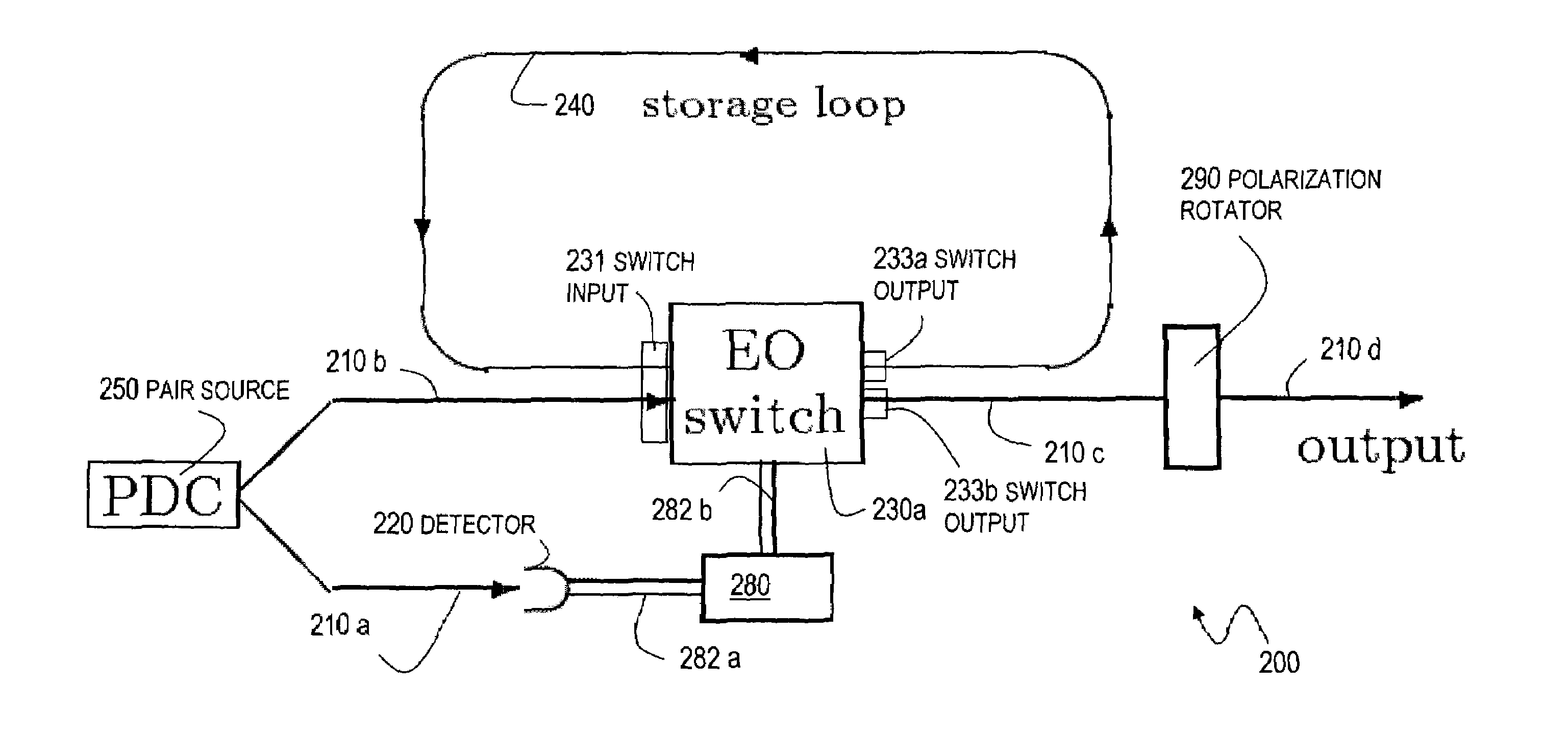
[0080]Embodiment 201 includes an EO switch 230b, and includes delay component 222 and optical paths 210e, 210f in optical path 210b.

[0081]EO switch 230b includes a polarizing beam splitter (PBS) 232 that reflects vertically polarized photons and transmits horizontally polarized photons incident along any of several spatial modes. One input mode of PBS 232 serves as one switch input 231a of switch inputs 231.

[0082]EO switch 230b also includes a Pockels cell (PC) 234 that is used to rotate the polarization of the photon circulating in the optical loop. The Pockels cell 234 is configured so that it does not affect a photon incident on the Pockels cell 234 unless the Pockels cell 234 is turned “on” by a classical pulse from the processor 280 of the controller. When it is turned on, the Pockels cell 234 rotates the polarization of an incident photon by 90 degrees (π / 2 radians) so that the single photon emerging from the Pockels cell 234 has a flipped polarization state. For example, a v...

embodiment 600

[0121]FIG. 6A is a block diagram that illustrates a storage and retrieval device used as a cyclical quantum memory (CQM) for a qubit represented by an arbitrary polarization state of a single photon, according to an embodiment 600. The CQM 600 involves an optical loop that includes a Sagnac interferometer switch 630 and a storage line 641.

[0122]The Sagnac interferometer switch 630 is formed with mirrors 644a, 644b, a polarizing beam splitter (PBS) 632, and an electro-optic (EO) device 634. The EO device is configured to do nothing in an off electrical state, and to swap vertical and horizontal polarization of an incident photon in an on electrical state. That is, when the EO device 634 is in an on electrical state, an incident photon with an arbitrary polarization state given by polarization state vector α|H]+β|V] is emitted with a swapped (“bit-flipped”) polarization state given by polarization state vector β|H]+α|V]. This rotation of horizontal polarization into vertical and verti...


PUM


Abstract

An optical switch and optical storage loop are used as the basis of a single-photon source and a quantum memory for photonic qubits. To operate as a single-photon source, the techniques include a source of a pair of photons, such as a parametric down-conversion crystal, which is known to emit photons in pairs. The detection of one member of the pair activates the switch, which re-routes the other member into the storage loop. The stored photon is then known to be circulating in the loop, and can be switched out of the loop at a later time chosen by the user, providing a single photon for potential use in a variety of quantum information processing applications. To operate as a quantum memory for photonic qubits, a single-photon in an arbitrary initial polarization state is coherently stored in the loop, and coherently switched out of the loop when needed.

Description

CROSS-REFERENCE TO RELATED APPLICATIONS[0001]This application claims benefit of Provisional Appln. 60 / 431,835, filed Dec. 9, 2002, the entire contents of which are hereby incorporated by reference as if fully set forth herein, under 35 U.S.C. §119(e).[0002]This application claims benefit of Provisional Appln. 60 / 433,072, filed Dec. 13, 2002, the entire contents of which are hereby incorporated by reference as if fully set forth herein, under 35 U.S.C. §119(e).[0003]This application is related to U.S. patent application, Ser. No. 10 / 286,735, by T. Pittman et al., filed Nov. 1, 2002 (hereinafter referenced as Pittman I), the entire contents of which are hereby incorporated by reference as if fully set forth herein.STATEMENT OF GOVERNMENTAL INTEREST[0004]This invention was made in part with Government support under Contract No. N0001-491-J1485 awarded by the Office of Naval Research. The Government has certain rights in the invention.BACKGROUND OF THE INVENTION[0005]1. Field of the Inv...

Claims


Application Information

Patent Timeline
Patent Type & Authority Patents(United States)
IPC IPC(8): G06E3/00G02B6/35G06N99/00
CPCB82Y10/00H04B10/70G06N99/002Y10S977/933G06N10/00G02F3/00
Inventor PITTMAN, TODD B.FRANSON, JAMES D.JACOBS, BRYAN C.
Owner THE JOHN HOPKINS UNIV SCHOOL OF MEDICINE
Why Eureka
Try Eureka