

Inter-atrial septum or superior vena cava electrodes for atrial defibrillation
- Summary
- Abstract
- Description
- Claims
- Application Information
AI Technical Summary
Benefits of technology
Problems solved by technology
Method used
Image

Examples
examples
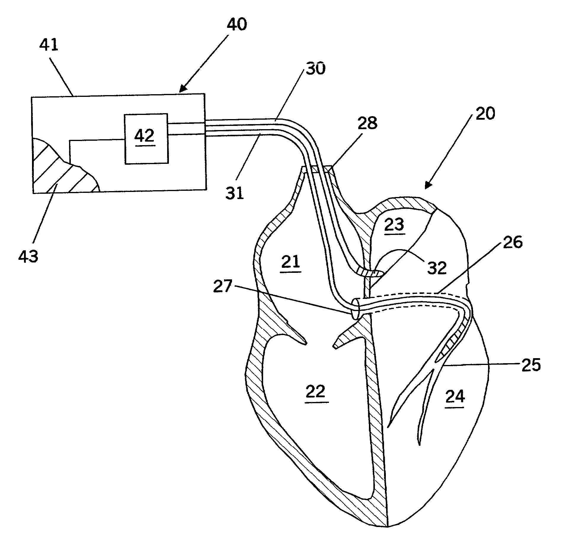
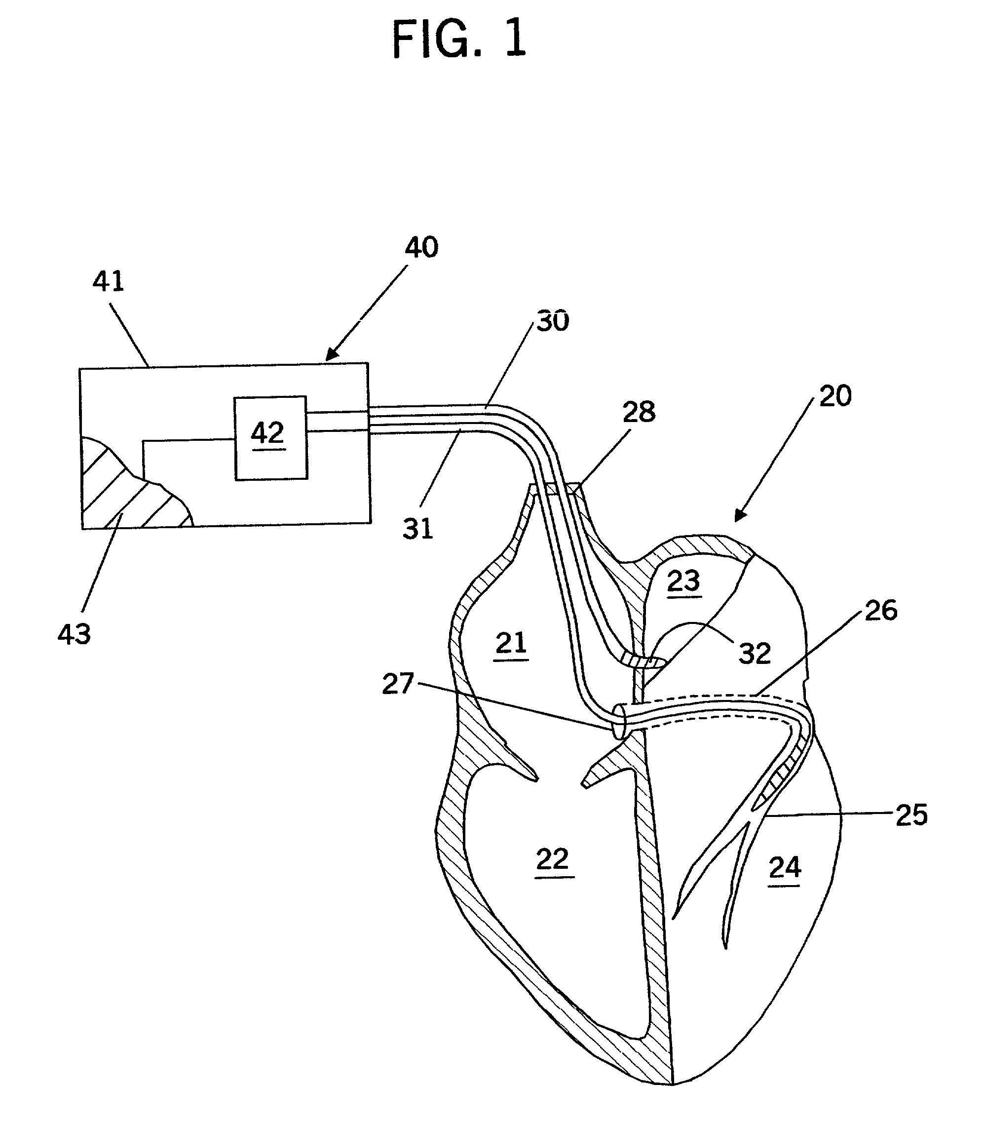
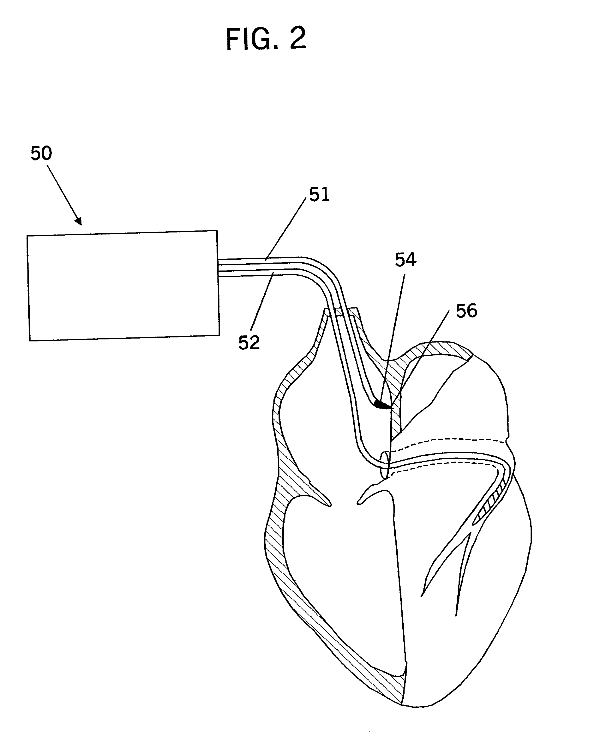
Reduction of Atrial Defibrillation Threshold With an Interatrial Septal Electrode
[0069]This example demonstrates that an electrode configuration with an interatrial septal electrode placed approximately midway between the right atrial appendage and coronary sinus electrodes increases the potential gradient in this region and thus lowers the atrial defibrillation threshold (ADFT).
I. Methods
[0070]All studies were performed in accordance with the guidelines established in the Position of the American Heart Association on Research Animal Use adopted by the American Heart Association on Nov. 11, 1984.
[0071]Of 11 adult sheep, 8 (41±6 kg, heart mass 217±8 g) completed the experimental protocol; only data from these 8 animals were compiled.
[0072]Animal Preparation. As a preanesthetic agent, a 1-to-1 mixture of tiletamine and zolazepam (8–10 mg / kg) was given intramuscularly. About 10 minutes later, thiopental (2–6 mg / kg) was administered as a slow intravenous bolus. The animal was laid in a ...
PUM
 Abstract
Description
Claims
Application Information