
Heat exchange system

a heat exchange system and heat exchange technology, applied in the direction of hot heat carrier steam generation, greenhouse gas reduction, lighting and heating apparatus, etc., can solve the problems of degrading the efficiency of heat recovery of internal combustion engines, increasing temperature, and difficulty in cooling the hottest section at the upstream end of the exhaust port sufficiently, so as to reduce the loss of thermal energy, suppress the dissipation of heat, and maintain the effect of heat exchange efficiency

Inactive Publication Date: 2006-04-04
HONDA MOTOR CO LTD
View PDF12 Cites 12 Cited by
  • Summary
  • Abstract
  • Description
  • Claims
  • Application Information

AI Technical Summary

Benefits of technology

This configuration enhances thermal energy recovery efficiency by effectively cooling the upstream section and maintaining heat exchange efficiency throughout the system, reducing thermal expansion and maintaining dimensional precision.

Problems solved by technology

However, in the above-mentioned conventional evaporator, since the flow of exhaust gas and the flow of water are opposite to each other, the temperature of water flowing through the water passage in the vicinity of the upstream end of an exhaust port (that is, the downstream end of the water passage) has already been increased, and it is difficult to cool the hottest section at the upstream end of the exhaust port sufficiently.
Because of this, the heat of the high temperature exhaust port dissipates via the cylinder head, and the efficiency of recovery of the waste heat of the internal combustion engine is degraded, which is a problem.
In order to avoid this problem, making the direction of flow of the exhaust gas and the direction of flow of the water parallel to each other enables the upstream end of the exhaust port, which reaches a high temperature, to be cooled effectively with low temperature water, but this results in an increase in the temperature of the water flowing through the downstream side of the exhaust port, where the temperature of the exhaust gas is low, and the temperature difference between the exhaust gas and water is therefore small in that section, thus degrading the heat exchange efficiency, which is a problem.

Method used


Image

  • Heat exchange system
  • Heat exchange system
  • Heat exchange system

Examples


Embodiment Construction

[0043]An embodiment of the present invention is explained below with reference to FIG. 1 to FIG. 23.

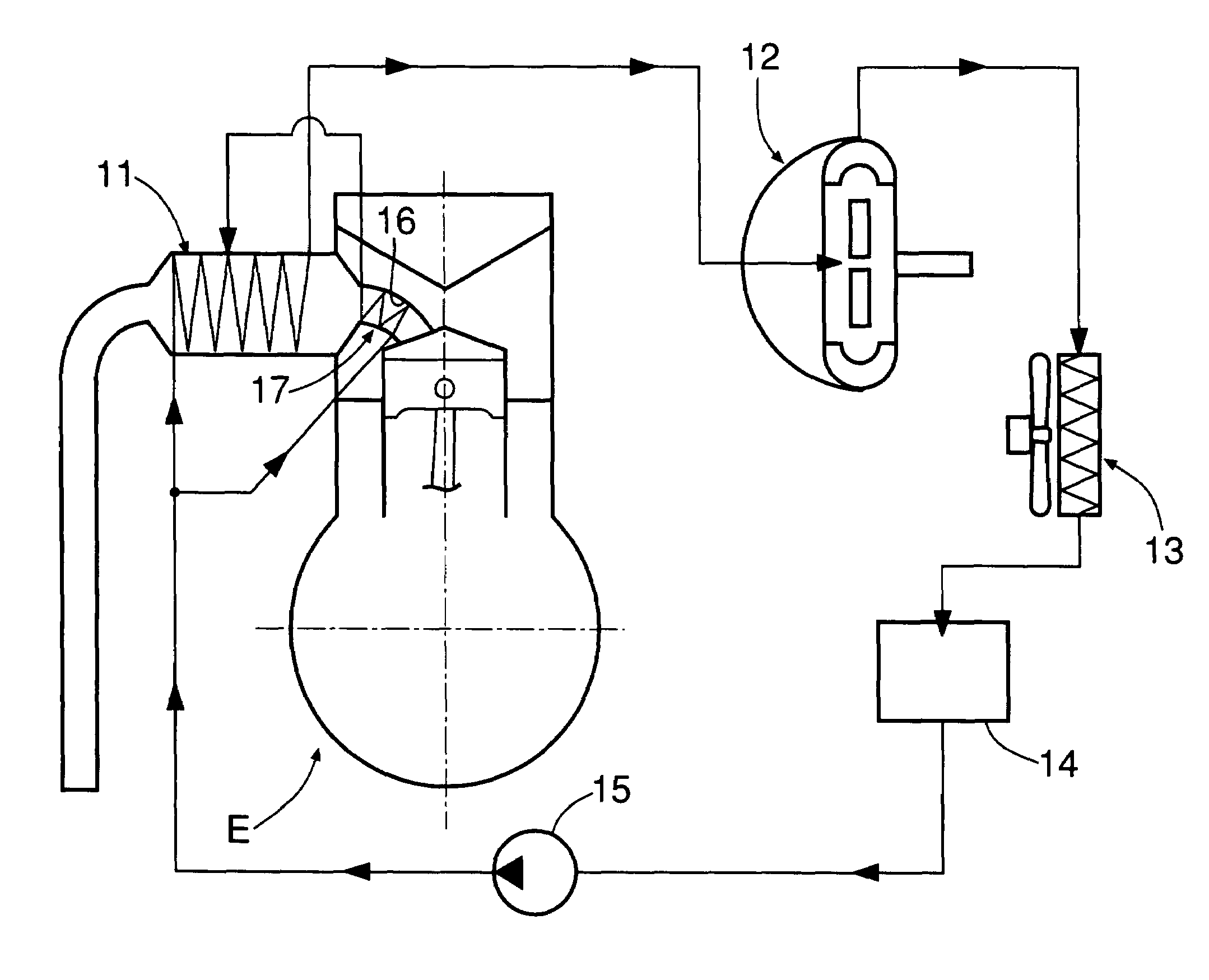
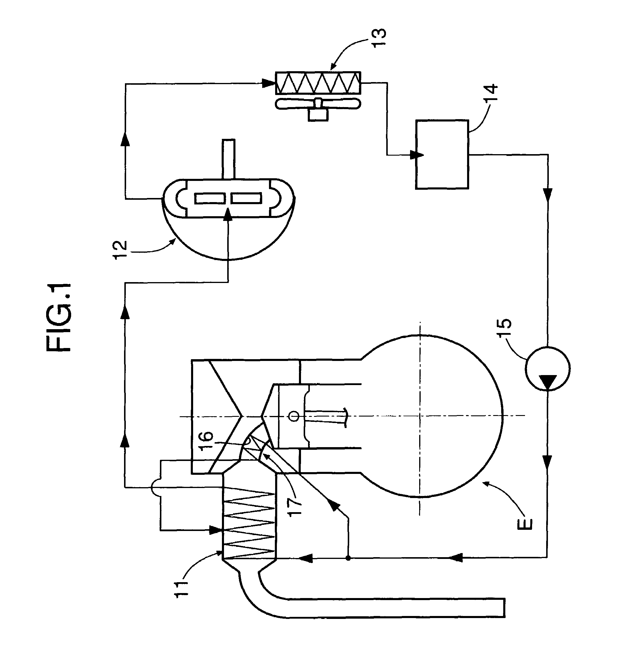
[0044]FIG. 1 shows the overall arrangement of a Rankine cycle system to which the present invention is applied.

[0045]The Rankine cycle system, which recovers the thermal energy of an exhaust gas of an internal combustion engine E and converts it into mechanical energy, includes a main evaporator 11 that heats water with exhaust gas discharged from the internal combustion engine E so as to generate high temperature, high pressure steam, an expander 12 that is operated by the high temperature, high pressure steam generated by the main evaporator 11 so as to generate mechanical energy, a condenser 13 that cools decreased temperature, decreased pressure steam that has completed work in the expander 12 so as to turn it back into water, a reservoir tank 14 for collecting water discharged from the condenser 13, and a supply pump 15 for pressurizing the water collected in the reservoir tank 1...


PUM


Abstract

A heat exchange system is provided in which low temperature water from a supply pump (15) is split and supplied to an auxiliary evaporator (17) provided so as to cover an exhaust port (16) extending from a combustion chamber of an internal combustion chamber (E) and to a main evaporator (11) provided downstream of the exhaust port (16). The direction of water flowing through the auxiliary evaporator (17) is parallel to the direction of flow of exhaust gas, and as a result an upstream section of the exhaust port (16), which has a high temperature, can be cooled effectively with low temperature water, and the escape of heat from the upstream section of the exhaust port (16) can be suppressed. The direction of water flowing through the main evaporator (11) is opposite to the direction of flow of exhaust gas, thus ensuring that there is a temperature difference between the water and the exhaust gas along the whole length of the water passage of the main evaporator (11) and enabling the heat exchange efficiency to be improved.

Description

FIELD OF THE INVENTION[0001]The present invention relates to a heat exchange system for recovering with a heat medium the thermal energy of a high temperature fluid flowing through the interior of a fluid passage extending from a heat source.BACKGROUND ART[0002]An evaporator that carries out heat exchange between exhaust gas of an internal combustion engine and water so as to heat the water by the heat of the exhaust gas and generate high temperature, high pressure steam is known from Japanese Patent Application Laid-open No. 2001-207839.[0003]This evaporator improves the heat exchange efficiency by making the water flow in a direction opposite to the direction of flow of the exhaust gas, which is discharged from a combustion chamber of the internal combustion engine, that is, from the downstream side to the upstream side of the flow of exhaust gas, thus ensuring that there is a temperature difference between the exhaust gas and the water along the whole of a water passage.[0004]How...

Claims


Application Information

Patent Timeline
Patent Type & Authority Patents(United States)
IPC IPC(8): F01K23/10F01N5/02F02G5/02F28D7/00F01N3/04F01P3/12F01P3/20F01P3/22F22B1/18F28D1/03F28D1/04F28F1/32
CPCF01N3/043F28D21/001F01N5/02F01P3/12F01P3/22F02G5/02F22B1/1807F28D7/1638F28F1/32F01N3/046F01N2240/02F01P2060/16Y02T10/16Y02T10/166Y02T10/20Y02E20/30Y02T10/12
Inventor SHINOHARA, MASASHIENDOH, TSUNEOBABA, ATSUSHI
Owner HONDA MOTOR CO LTD
Learn More