Projector

a projector and optical element technology, applied in the field of projectors, can solve the problems of unstable image, high cost driving circuit, and inability to easily secure the stable operation of phase modulating optical elemen

Inactive Publication Date: 2006-04-04
SEIKO EPSON CORP
View PDF11 Cites 11 Cited by
  • Summary
  • Abstract
  • Description
  • Claims
  • Application Information

AI Technical Summary

Benefits of technology

[0008]Therefore, exemplary aspects of the present invention provide a projector able to form a projecting image having smooth image quality and high resolution, being inconspicuous in the joint, being stable and being able to switch and display the projecting image.

Problems solved by technology

However, in the above projector, since the phase modulating optical element is switched and operated during one frame period, no stable operation of the phase modulating optical element can be easily secured, and the phase modulating optical element and its driving circuit become expensive.
Otherwise, the obtained image tends to be unstable.
Accordingly, a reduction in brightness of the projecting image and brightness irregularities are inevitably caused.

Method used


Image

  • Projector
  • Projector
  • Projector

Examples


first exemplary embodiment

[0032 Mode

[0033]The structure of a projector in accordance with a first exemplary embodiment mode of the present invention will next be explained with reference to the drawings.

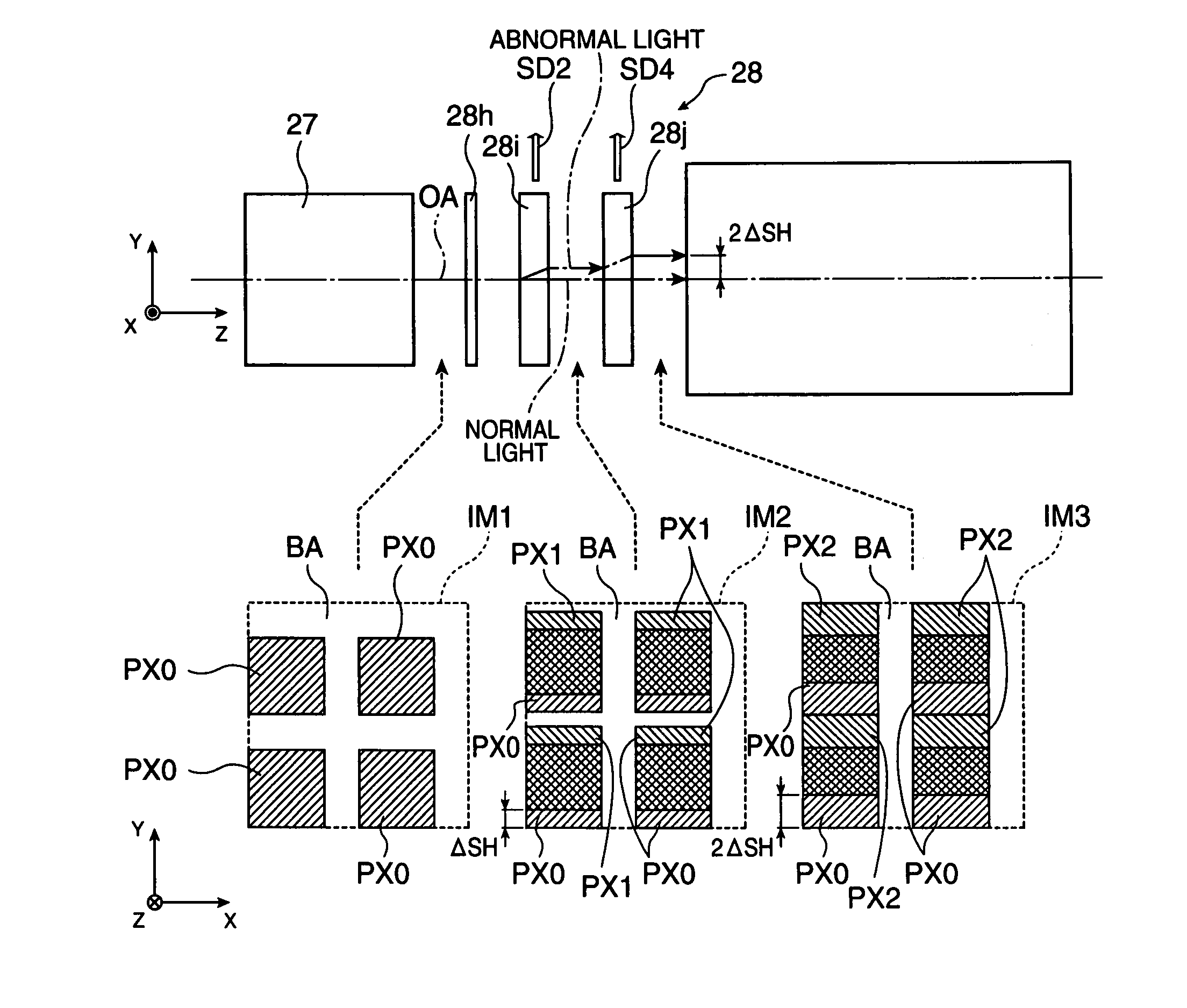
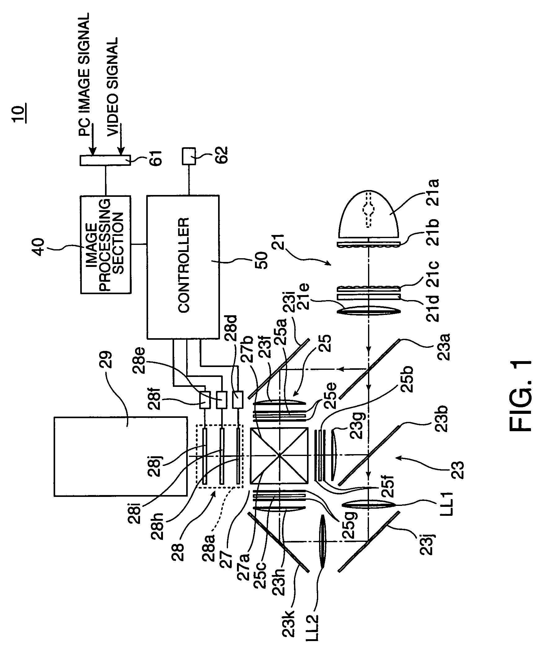
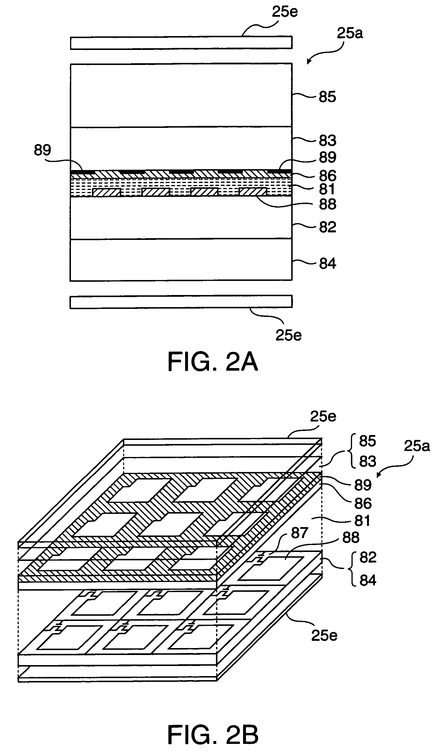
[0034]FIG. 1 is a schematic for explaining an optical system of the projector of the first exemplary embodiment mode. This projector 10 has a light source device 21 to generate light source light, a light division optical system 23 to divide the light source light from the light source device 21 into three colors of RGB, and a light modulating section 25 illuminated by illumination light of each color emitted from the light division optical system 23. The projector 10 also has a light synthesizing optical system 27 to synthesize image light of each color from the light modulating section 25, a BM removing unit 28 to perform one kind of optical low pass filter processing with respect to the image light synthesized by the light synthesizing optical system 27 in its operating state, and a projecting lens 29 as a...

second exemplary embodiment

[0054 Mode

[0055]FIG. 8 is a schematic for explaining a projector of a second exemplary embodiment mode. The projector of the second exemplary embodiment mode is formed by modifying the projector of the first exemplary embodiment mode. The same portions of the projector as the first exemplary embodiment mode are designated by the same reference numerals, and their overlapping explanations are omitted here. Further, portions particularly unexplained can be constructed similarly to those in the first exemplary embodiment mode.

[0056]In this case, the image light emitted from the liquid crystal light valves 25a, 25c for RB lights is set to S-polarized light vibrated in the direction perpendicular to the incident face perpendicular to both the dielectric multilayer films 27a, 27b. However, the image light emitted from the liquid crystal light valve 25b for G-light is set to P-polarized light vibrated within the above incident face. Therefore, the light source light taken out of the light ...

third exemplary embodiment

[0061 Mode

[0062]FIG. 11 is a schematic for explaining a projector of a third exemplary embodiment mode. The projector of the third exemplary embodiment mode is formed by modifying the projector of the first exemplary embodiment mode. Portions particularly unexplained can be constructed similarly to those in the first embodiment mode.

[0063]This projector 110 has the BM removing unit 28 for each color of RGB at the first half stage of the cross dichroic prism 27. The black matrix area BA can be independently erased every each color of RGB by setting such a construction. Specifically, a various expression considering color characteristics can be also made since the ratio of branching light can be adjusted every each color of RGB and the shift amount of the branching light can be adjusted for each color of RGB. Actuators 28d to 28f (see FIG. 1) for operating the birefringent plates 28i, 28j and the λ / 2 phase difference plate 28h are arranged for each BM removing unit 28 although these a...


PUM

PropertyMeasurementUnit
angleaaaaaaaaaa
angleaaaaaaaaaa
angleaaaaaaaaaa

Abstract

An object of the invention is to form a projecting image of smooth image quality inconspicuous in a joint in a stable state. With respect to image light passing through a second birefringent plate 28j set to a first state, an image light portion branched by a first birefringent plate 28i is further branched in the Y-direction. An image IM3 constructed by an original pixel PX0, a pixel PX2 corresponding to its branching image, and a black matrix area BA is formed on a screen. With respect to the image light passing through a second birefringent plate 28j set to a second state, the image light once branched by the first birefringent plate 28i is returned in the −Y direction. As this result, an image constructed by the black matrix area BA and an image provided by overlapping the branching image of the original pixel PX0 with the original pixel PX0 is formed on the screen. Namely, the same image IM3′ as an original image IM1 is formed on the screen.

Description

BACKGROUND OF THE INVENTION[0001]1. Field of Invention[0002]Exemplary aspects of the present invention relate to a projector to project an image by using a liquid crystal display panel and other display elements.[0003]2. Description of Related Art[0004]A related art projector is assembled having a display element constructed by a discrete pixel, and an optical device of a structure laminating plural wobbling elements, each constructed by an optically transparent birefringent medium and an optically transparent phase modulating optical element of a switch type constructed by a ferroelectric liquid crystal, etc. See Japanese Patent Application No. 7-36054.[0005]In such a projector, the polarizing direction of light passing through the birefringent optical element is alternately switched in the perpendicular direction by switching the operation of the phase modulating optical element within one frame. Thus, an optical path of the light emitted via the phase modulating optical element a...

Claims


Application Information

Patent Timeline
Patent Type & Authority Patents(United States)
IPC IPC(8): G03B21/14G02B27/00G02B27/14G02B27/28G02F1/1335G03B21/26
CPCG02B27/1046H04N9/3141G02B27/149G02B27/286G02B27/288G03B21/00G03B21/14G03B33/12G09G3/002G09G3/007H04N9/3105G02B27/145G02F1/133509G09G2320/0606G09G2320/0613G03B21/005G03B21/208G02B27/28
Inventor UEHARA, KATSUYUKI
Owner SEIKO EPSON CORP
Why Eureka
Try Eureka