Rear projection optical system

a projection optical system and optical system technology, applied in the field of rear projection optical systems, can solve the problems of difficult to slim down the apparatus below a certain thickness, entail high cost, and the projection optical system itself is larger, and achieves the effect of high imaging performan

Inactive Publication Date: 2006-04-04
MINOLTA CO LTD
View PDF25 Cites 10 Cited by
  • Summary
  • Abstract
  • Description
  • Claims
  • Application Information

AI Technical Summary

Benefits of technology

[0017]An object of the present invention is to provide an oblique projection optical system that offers high imaging performance and that permits further miniaturization not only in the direction perpendicular to the screen but also in the direction along the screen.

Problems solved by technology

This makes it difficult to slim down the apparatus below a certain thickness.
Such an optical system can be realized, but it entails high cost, and in addition makes the projection optical system itself larger, with little effect of slimming down the apparatus.
As long as a long optical path length is secured to prevent the lowering of imaging performance, it is difficult to reduce the height dimension of the screen without sacrificing the flatness of the apparatus.
Thus, modern oblique projection optical systems are considered to have almost reached the limit in terms of the trade-off between the slimming-down of projection apparatus and the reduction of the height dimension thereof.
This makes it difficult to slim down rear projection optical systems below a certain thickness.
However, with conventional rear projection optical systems, sufficient slimming-down is difficult, or slimming them down poses new problems.
This inevitably makes the projection optical system large.
In addition, this method requires an oblique projection optical system that permits the ray striking the center of the screen surface to be incident thereon at a large angle of incidence, but the publication describes no specific optical arrangement of such an optical system.
However, to slim down a rear projection optical system, the projection angle of the principal ray needs to be made very large.
In general, a wide-angle optical system requires a large number of lens elements, and their lens diameters are very large.
In these display apparatus, however, the light that has exited from the projection optical system is reflected directly by a flat-surface reflecting mirror arranged behind a screen, and thus the curved-surface reflecting mirror that constitutes the last surface of the projection optical system needs to be very large.
A large curved-surface reflecting mirror like this is disadvantageous in terms of mass production and cost.
Moreover, if the projection optical system includes only three curved-surface mirrors, it is highly sensitive to errors, and is thus difficult to manufacture.

Method used


Image

  • Rear projection optical system
  • Rear projection optical system
  • Rear projection optical system

Examples


seventh embodiments

First to Seventh Embodiments

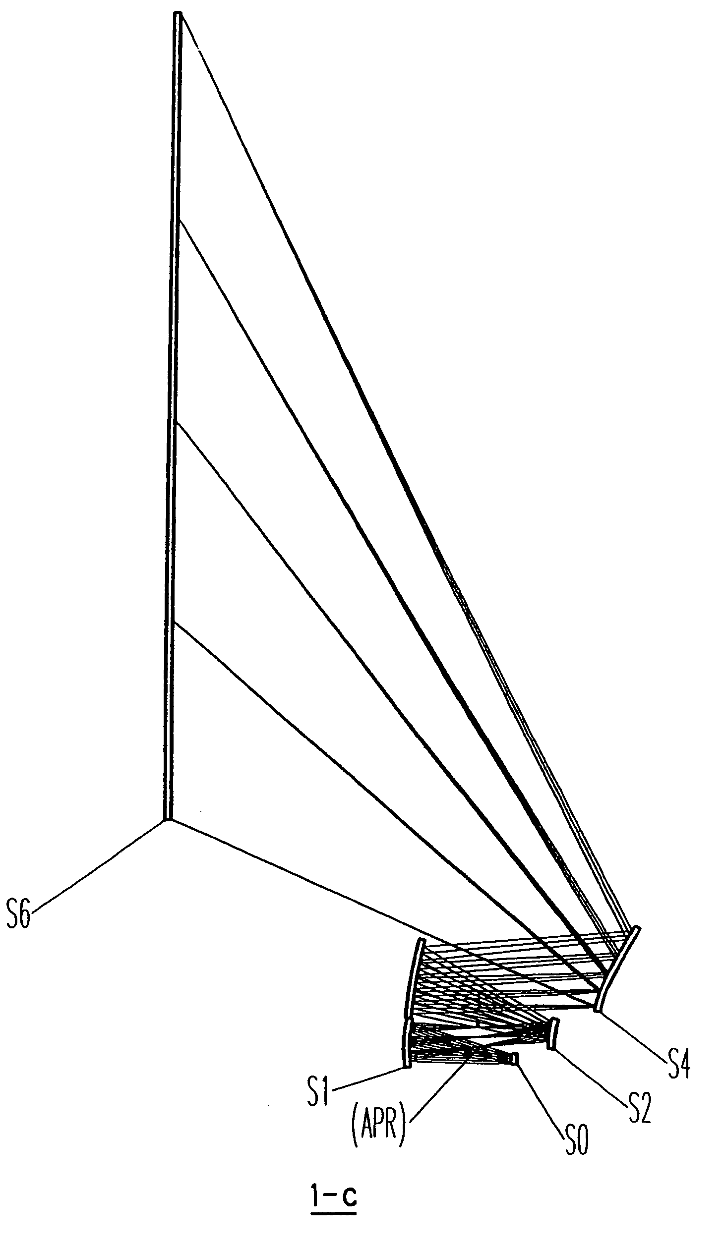
[0075]First, as a first to a seventh embodiment of the invention, practical examples (Examples 1 to 7, respectively) of oblique projection optical systems will be presented below with reference to their actual construction data and other data. The oblique projection optical systems 1 to 7 of Examples 1 to 7 are all composed of four powered curved-surface mirrors and one non-powered flat-surface mirror. These oblique projection optical systems 1 to 7 are all designed to lead rays of light from a rectangular display surface having longer sides in the width direction thereof to a projection surface by reflecting the rays with the individual mirrors in such a way as to deflect the rays in the height direction of the display surface and make the rays converge on the projection surface. As a result, a magnified image of the image displayed on the display surface is formed (projected) on the projection surface, in a rectangular area thereon that is substantially...

example 1

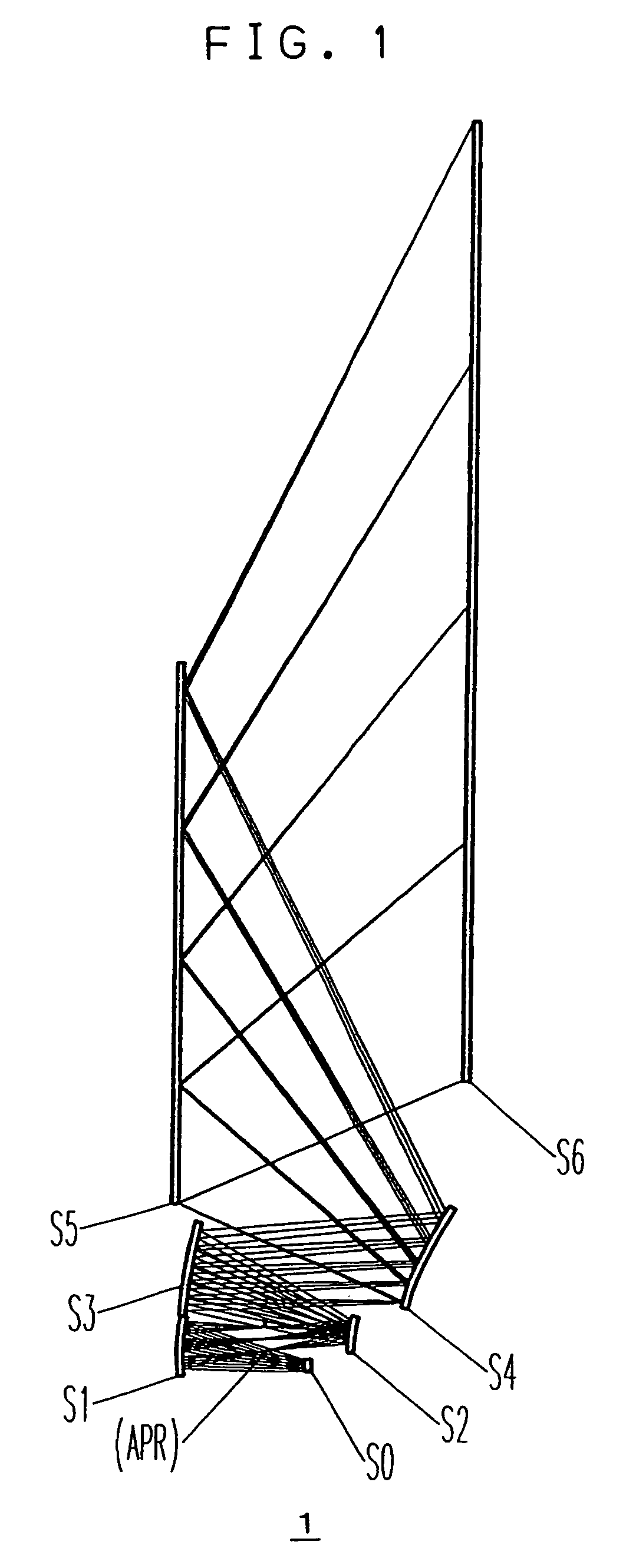
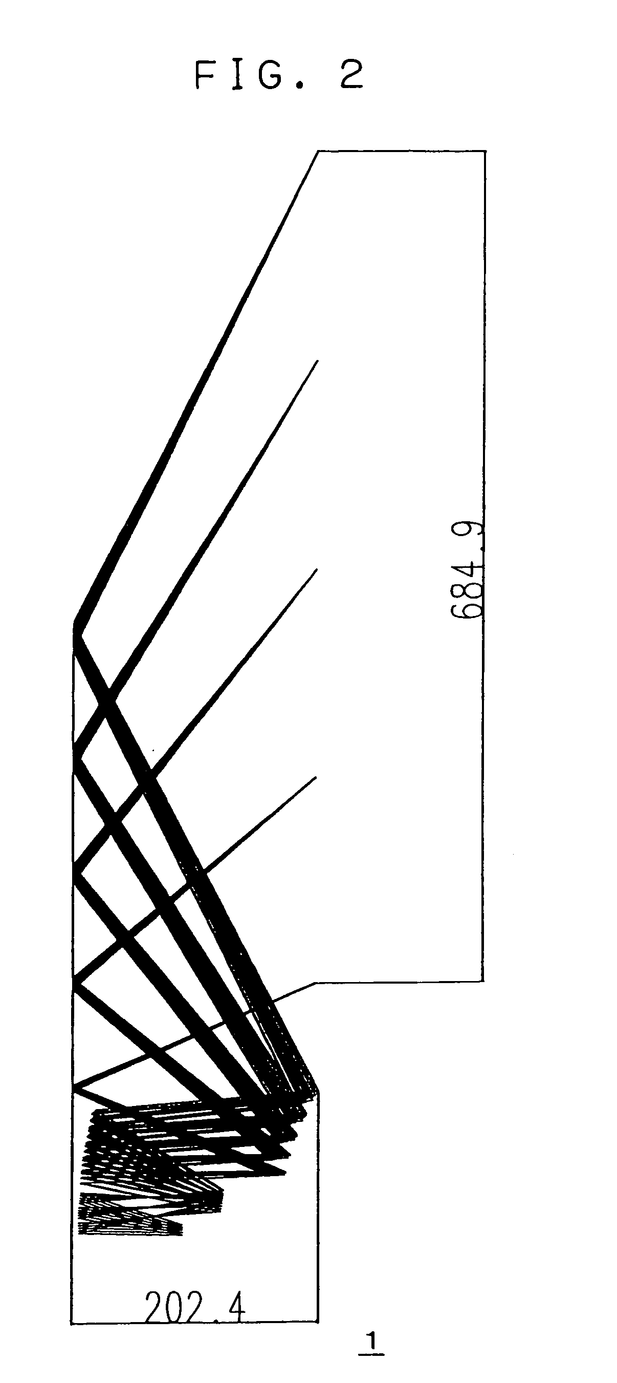
[0081]FIGS. 1 to 4 show the construction and optical path of the oblique projection optical system 1 of Example 1, and Tables 3 to 10 show the construction data thereof. Tables 3 to 10 each list the data of the surface referred to by the symbol noted at the top of the table. N0 and N1 respectively represent the refractive indices of the media before incidence and after incidence (i.e. after reflection) on a surface. “Position” indicates the position of the origin of the corresponding local coordinate system in the absolute coordinate system. In Table 5, which lists the data of the pupil plane APR, R represents the radius of the pupil (aperture stop).

[0082]It is to be noted that, also in the other examples described later, what their construction data represents is the same as with Tables 3 to 10.

[0083]FIG. 1 is a sectional view taken along the x-y plane, and shows the surfaces S0 to S6 together with, among the rays emanating from the center in the width direction of the display surf...

modified example 1 of example 1

[0096]FIGS. 7 and 8 show a sectional view and a top view, respectively, of the oblique projection optical system 1-b of a modified example of the oblique projection optical system 1 of Example 1. The oblique projection optical system 1-b differs from its base model in that the surfaces starting with the display surface S0 and ending with the flat-surface reflecting surface S5 are shifted toward the projection surface S6.

[0097]As will be clear from FIG. 7, the greater part of the reflecting surface S4 is located opposite to the flat-surface reflecting surface S5 with respect to the projection surface S6, and thus a lower central portion of the oblique projection optical system 1-b protrudes a little from the projection surface S6. As a result, as shown in Table 2 described earlier, the thickness D of the optical path in the optical system as a whole is larger, but, as will be understood through comparison between FIGS. 7 and 1, the distance between the projection surface S6 and the f...


PUM


Abstract

An oblique projection optical system for leading rays of light from a display surface on which an image is displayed to a projection surface in such a way that the ray of light from the center of the display surface is obliquely incident on the projection surface in order to project a magnified image of the image displayed on the display surface onto the projection surface includes a plurality of reflecting surfaces having a power. At least two of the reflecting surfaces have a free-form curved surface, and, of all the reflecting surfaces, the one closest to the projection surface has a negative power and at least one of the other has a positive power. Alternatively, in a rear projection optical system having a projection optical system for projecting an image displayed on a panel display surface onto a screen surface, the projection optical system includes at least four curved-surface reflecting mirrors.

Description

[0001]This application is a continuation of U.S. patent application Ser. No. 10 / 151,342, filed May 20, 2002, now U.S. Pat. No. 6,779,897 which claimed priority from Japanese Patent Application Nos. 2001-363653 and 2000-34319 filed on Nov. 29, 2001 and Feb. 7, 2002 respectively, the contents of which are hereby incorporated by reference.BACKGROUND OF THE INVENTION[0002]1. Field of the Invention[0003]The present invention relates to a projection optical system for projecting a magnified image on a screen, and to a rear projection optical system provided with such a projection optical system. More specifically, the present invention relates to an oblique projection optical system and a rear projection optical system that shine a beam of light on a screen from an oblique direction.[0004]2. Description of the Prior Art[0005]From long ago, it has been common practice to project a magnified image of an image displayed on a small display surface onto a screen. Before, projection of an image...

Claims


Application Information

Patent Timeline
Patent Type & Authority Patents(United States)
IPC IPC(8): G03B21/28G02B13/18G02B17/00G03B21/00G03B21/10
CPCG02B17/0663G03B21/10G03B21/00G03B21/005
Inventor KONNO, KENJIOHZAWA, SOHISHIHARA, JUN
Owner MINOLTA CO LTD
Why Eureka
Try Eureka