CMP pad conditioner having working surface inclined in radially outer portion

a technology of working surface and conditioner, which is applied in the direction of gear-teeth manufacturing apparatus, abrasive surface conditioning devices, lapping machines, etc., can solve the problems of insufficient cleaning of pad surface, high spot on pad surface, and easy wear of the conditioning disk, so as to facilitate the evacuation of swarf and improve the condition performan

Active Publication Date: 2006-04-04
NORITAKE CO LTD +1
View PDF13 Cites 57 Cited by
  • Summary
  • Abstract
  • Description
  • Claims
  • Application Information

AI Technical Summary

Benefits of technology

[0011]The present invention was made in view of the background prior art discussed above. It is therefore an object of the invention to provide a CMP pad conditioner capable of avoiding considerable damage of abrasive grains in its peripheral or radially outer portion and conditioning evenly over an entire surface of a CMP pad without causing the surface of the CMP pad to suffer from a local wear. This object may be achieved according to any one of first through twelfth aspects of the invention which are described below.
[0024]In the conditioner defined in any one of the first through twelfth aspects of the invention, in which the ratio of the outside diameter of the radially inner portion to the outside diameter of the disk-shaped substrate is 60–85%, it is possible to substantially avoid concentration of load onto ones of the abrasive grains located in the radially outer portion of the substrate, thereby preventing wear and fracture of the ones of the abrasive grains located in the radially outer portion, and leading to increase in lifetime of the conditioner. Further, since the wear and fracture of the abrasive grains are thus prevented, it is possible to maintain flatness in the profile of the CMP pad and prevent any local wear in the surface of the CMP, thereby enabling the CMP pad to exhibit an increased polishing rate and to have a prolonged lifetime. Still further, since the flatness in the profile of the CMP pad is thus maintained, a thickness of abrasive slurry (that is to be interposed between the CMP pad and the workpiece) can be made constant, thereby making it possible to significantly reduce micro-scratches given in the workpiece.
[0028]In the conditioner defined in any one of the ninth through twelfth aspects of the invention, since the abrasive layer formed on the working surface of the substrate is divided into the plurality of abrasive segments by the plurality of slots or grooves, the conditioning performance can be further improved owing to the grooves which facilitates evacuation of swarf (small chips and removed abrasive grains) from the conditioning area therethrough and also introduction of the abrasive slurry into the conditioning area therethrough.
[0029]In the conditioner defined in the eleventh or twelfth aspect of the invention, since the above-described grooves including the grooves each of which is inclined with respect to the radial direction of the disk-shaped substrate such that the radially outer end of the inclined groove is positioned on the rear side of the radially inner end of the inclined groove as viewed in the rotating direction, the evacuation of the swarf through the thus inclined groove (which is caused by the rotation of the conditioner) can be made more efficiently.

Problems solved by technology

However, when this conventional conditioning disk is used for conditioning a polishing pad having an elasticity, the conditioning disk suffers from a problem that ones of the abrasive grains 73 located at a peripheral part of the annular portion 72 tends to be easily worn, since a large load acts on the ones of the abrasive grains 73 located at the peripheral part.
That is, it would be impossible to sufficiently clean the pad surface and remove high spots on the pad surface.
In other words, the conditioning disk could no longer serve as a conditioner.
However, since the flat or non-curved portion of the working surface is narrow, the conditioner cannot perform a conditioning operation at a high efficiency.
Further, since the abrasive grains located on a relatively outer portion of the working surface of the disk-shaped substrate tend to be worn earlier than those located on a relatively inner portion of the working surface of the substrate, the pad is likely to suffer from a wear in a local portion of its surface, which could lead to a reduction in the pad lifetime.
However, feeing the conditioner along the denser path requires a larger length of time as a conditioning time, and is not therefore practicable.

Method used


Image

  • CMP pad conditioner having working surface inclined in radially outer portion
  • CMP pad conditioner having working surface inclined in radially outer portion
  • CMP pad conditioner having working surface inclined in radially outer portion

Examples


first embodiment

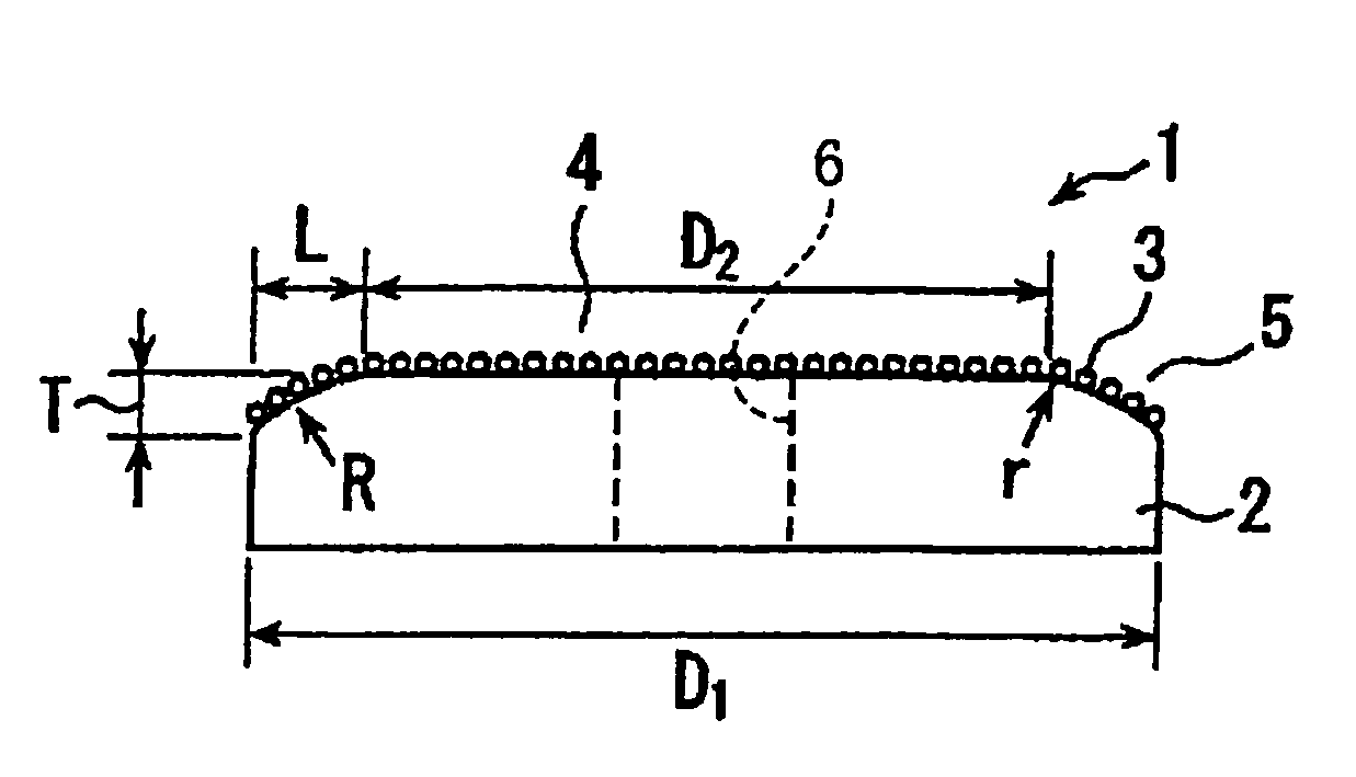
[0037]Referring first to FIG. 1, there will be described a CMP pad conditioner in the form of a rotary conditioning disk 1 which is constructed according to the invention. This conditioning disk 1 includes: a disk-shaped metal substrate 2 having a working surface which is provided by one of its axially opposite end surfaces; and abrasive grains 3 which are fixed to an entirety of the working surface of the metal substrate 2. The metal substrate 2 includes a radially inner portion 4 and a radially outer portion 5 which is located radially outwardly of the radially inner portion 4. The disk-shaped metal substrate 2 is provided by an annular body, and a center hole 6 formed therethrough. The working surface in the radially inner portion 4 is parallel with a plane perpendicular to an axial direction of the metal substrate 2, such that a thickness of the radially inner portion 4 as measured in the axial direction is substantially constant. The working surface in the radially outer portio...

second embodiment

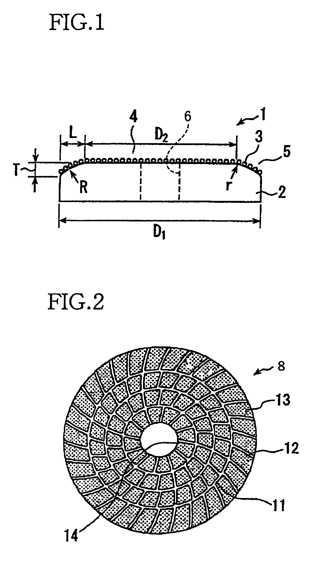
[0041]FIG. 2 shows another rotary conditioning disk 8, which is constructed according to the invention. This rotary conditioning disk 8 is substantially identical with the above-described rotary conditioning disk 1 except that an abrasive layer 13 is divided into a plurality of segments by a plurality of slots or grooves 11, 12 which are formed to extend along the working surface of the metal substrate 2.

[0042]Described specifically, the plurality of grooves 11, 12 includes first grooves 11 each of which extends substantially in a circumferential direction of the disk-shaped metal substrate 2, and second grooves 12 each of which extends in a direction away from a center hole 14 (farmed through the metal substrate 2) toward the periphery of the metal substrate 2. Each of the second grooves 12 is inclined with respect to a radial direction of the metal substrate 2, such that a radially outer end of each second groove 12 is positioned on a rear side of a radially inner end of the secon...

example 1

[0044 is identical with the above-described conditioning disk 1 of FIG. 1, wherein the ratio of the outside diameter of the radially inner portion of the metal substrate to the outside diameter of the metal substrate is 80%, while the difference amount between the thickness of the radially inner portion of the metal substrate and the thickness of the radially outer end of the metal substrate is equal to the average size of the abrasive grains.

[0045]Example 2 is identical with Example 1, except that the metal substrate further has the first and second grooves, as in the above-described conditioning disk 8 of FIG. 2.

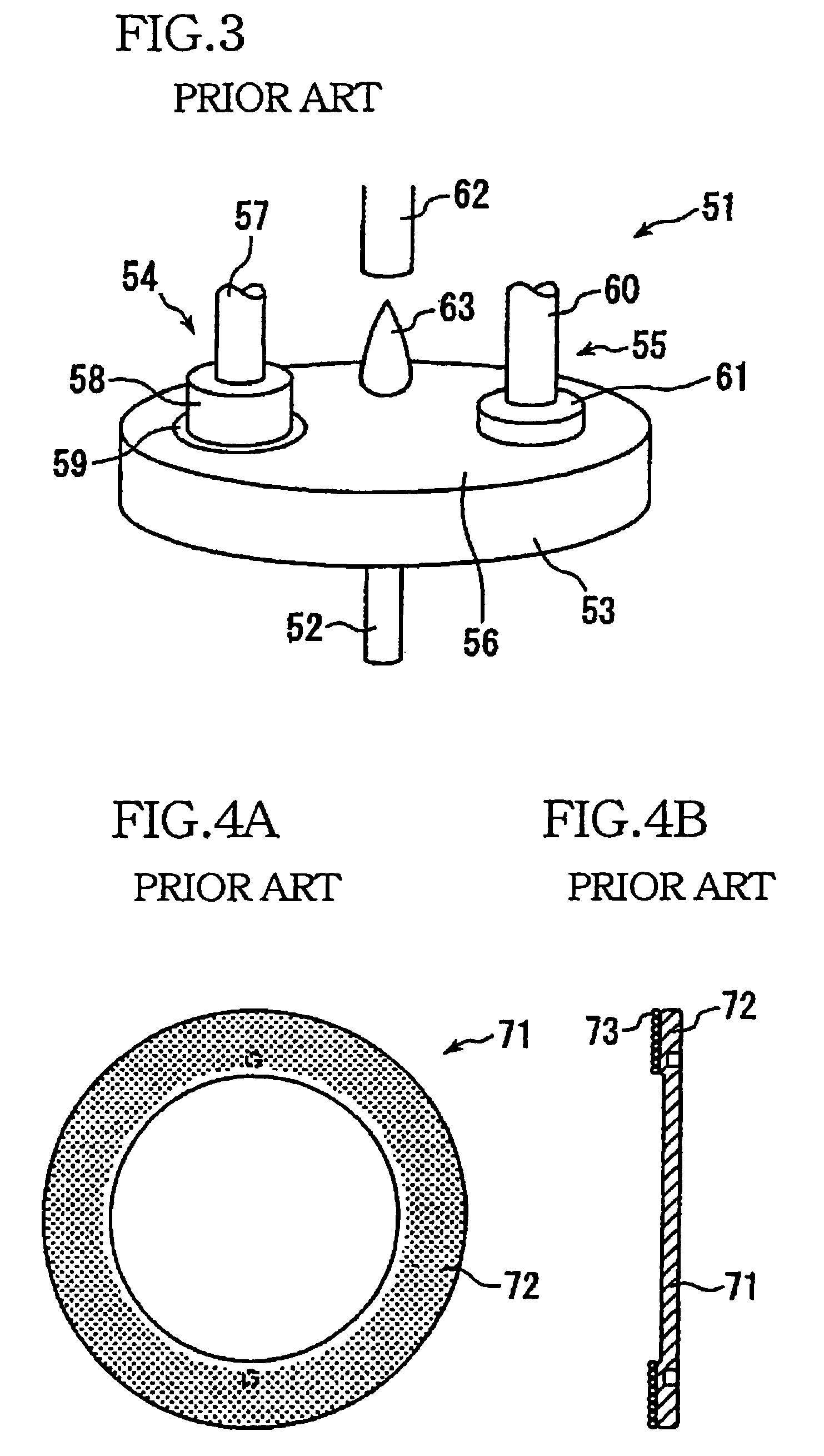
[0046]Comparative Example 1 is identical with the above-described conventional conditioning disk shown in FIGS. 4A and 4B.

[0047]Comparative Example 2 is identical with the conditioning disk disclosed in JP-A-2001-113456, wherein super abrasive grains 75 each having obtuse cutting edges are fixed to a radially inside portion of the working surface of the disk-shaped metal s...


PUM

PropertyMeasurementUnit
diameter D2aaaaaaaaaa

Abstract

A CMP pad conditioner including: (a) a disk-shaped substrate having a working surface which is provided by one of its axially opposite end surfaces and which is to be brought into contact with the CMP pad; and (b) abrasive grains which are fixed to the working surface. The substrate includes a radially inner portion and a radially outer portion which is located radially outwardly of the radially inner portion. The working surface in the radially outer portion is inclined with respect to the working surface in the radially inner portion, such that a thickness of the radially outer portion as measured in an axial direction of the substrate is reduced as viewed in a direction away from an axis of the substrate toward a periphery of the substrate. A ratio of an outside diameter of the radially inner portion to an outside diameter of the substrate is 60–85%.

Description

BACKGROUND OF THE INVENTION[0001]1. Field of the Invention[0002]The present invention to a CMP pad conditioner which is used for smoothing and planarizing a surface of a workpiece such as silicon wafer in a CMP apparatus.[0003]2. Discussion of the Related Art[0004]In recent years, as a process of smoothing and planarizing a surface of a silicon wafer or the like, there is commonly practiced a chemical mechanical polishing (herein after referred to as “CMP”) process.[0005]FIG. 3 shows a conventional CMP apparatus 51 including: a rotary table 53 which is to be rotated about its axis by a drive shaft 52; an polishing unit 54 which is disposed above the rotary table 53; a conditioning unit 55 which is disposed above the rotary table 53; and a polishing pad 56 which is formed on an upper surface of the rotary table 53.[0006]The polishing unit 54 includes a polishing spindle head 57 and a disk-shaped wafer carrier 58 having a lower surface to which a wafer 59 as a workpiece is to be fixed...

Claims


Application Information

Patent Timeline
Patent Type & Authority Patents(United States)
IPC IPC(8): B24B1/00B24B53/14B24B37/04B24B53/017B24B53/12H01L21/304
CPCB24B53/12B24B53/017
Inventor TOGE, NAOKIINOUE, YASUAKI
Owner NORITAKE CO LTD
Why Eureka
Try Eureka