Guidable intravascular blood pump and related methods

a blood pump and guide wire technology, applied in the field of blood pumps, can solve the problems of lysis or cell destruction, red blood cells are particularly susceptible to shear stress damage, prior art intravascular blood pumps suffer various drawbacks

Inactive Publication Date: 2006-04-04
MAQUET CARDIOVASCULAR LLC
View PDF33 Cites 550 Cited by
  • Summary
  • Abstract
  • Description
  • Claims
  • Application Information

AI Technical Summary

Benefits of technology

[0009]The present invention overcomes the drawbacks of the prior art by providing an improved intravascular blood pump equipped with integrated features for selectively guiding the intravascular blood pump to a predetermined location in the patient's circulatory system, i.e. heart and / or vasculature. In so doing, the intravascular blood pump of the present invention eliminates the need for supplemental guiding mechanisms, such as a separate, large diameter guide catheter as used in the prior art.
[0012]In a third broad aspect of the present invention, an intravascular blood pump system is provided comprising an intravascular blood pump having a cannula coupled thereto and a “guide catheter” type guide mechanism for selectively positioning the intravascular blood pump and cannula at a predetermined location within the circulatory system of a patient. The pump system of this broad aspect includes a conduit assembly and a separate pump assembly. The conduit assembly includes a guide catheter, a rotor shroud, and a cannula, with the cannula and guide catheter disposed on either side of the rotor shroud. The pump assembly includes a rotor, a drive member coupled to the rotor, and a pump disposed between the rotor and the drive member. The guide catheter is dimensioned to receive and guide the pump assembly to the point where the rotor docks within the rotor shroud so as to form an operational blood pump. This configuration allows the conduit assembly to be precisely and efficiently guided into a desired position within the body through the use of conventional guiding techniques well known in interventional cardiology. The pump assembly may thereafter be introduced into and guided within the conduit until the pump assembly is docked within the rotor shroud. This dual construction arrangement provides improved placement of the pump assembly by using the conduit as a guiding mechanism.

Problems solved by technology

It is well known to those skilled in the art that lysis or cell destruction may result from application of shear stress to cell membranes.
Red blood cells are particularly susceptible to shear stress damage as their cell membranes do not include a reinforcing cytoskeleton to maintain cell shape.
While generally effective in providing ventricular assisting functions, prior art intravascular blood pumps nonetheless suffer various drawbacks.
A significant drawback is that prior art intravascular blood pumps are difficult to guide into the appropriate position within the circulatory system of a patient.
This is due largely to the fact that the elongated catheter is incapable of providing the degree of control necessary to easily negotiate the pump through the tortuous pathways leading up to and into the heart.
When attempting to place the blood pump in a trans-valvular configuration (with the inlet in the left ventricle and the pump outlet in the ascending aorta), the natural tendency of the catheter to stay straight may cause the pump to be inadvertently placed in the carotid ostia, which can be dangerous if the pump is operated to withdraw blood from the brain.
While generally effective at providing a guiding feature for such intravascular blood pumps, employing such supplemental guide mechanisms is nonetheless disadvantageous in that they consume valuable space within the vessels.
As will be appreciated, this restricts the amount of space available for blood to flow within the particular vessel, and increases the size of the required puncture wound for accessing the vessel.

Method used


Image

  • Guidable intravascular blood pump and related methods
  • Guidable intravascular blood pump and related methods
  • Guidable intravascular blood pump and related methods

Examples


Embodiment Construction

[0056]Illustrative embodiments of the invention are described below. In the interest of clarity, not all features of an actual implementation may be described in this specification. It will of course be appreciated that in the development of any such actual embodiment, numerous implementation-specific decisions must be made to achieve the developers' specific goals, such as compliance with system-related and business-related constraints, which will vary from one implementation to another. Moreover, it will be appreciated that such a development effort might be complex and time-consuming, but would nevertheless be a routine undertaking for those of ordinary skill in the art having the benefit of this disclosure.

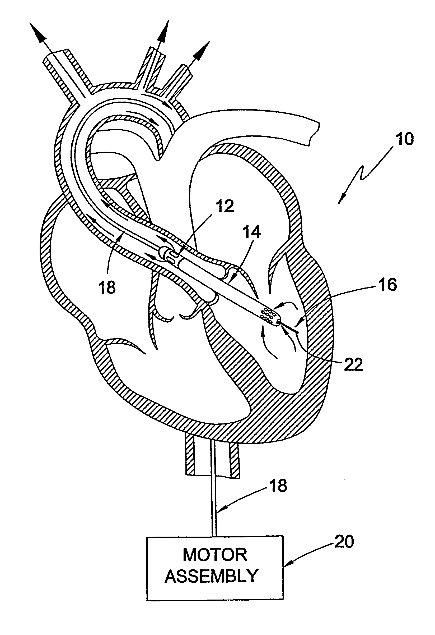
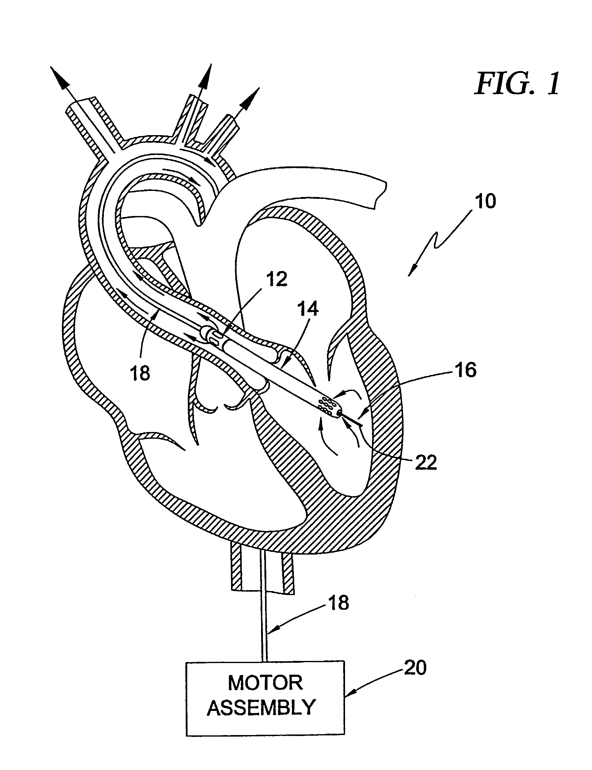
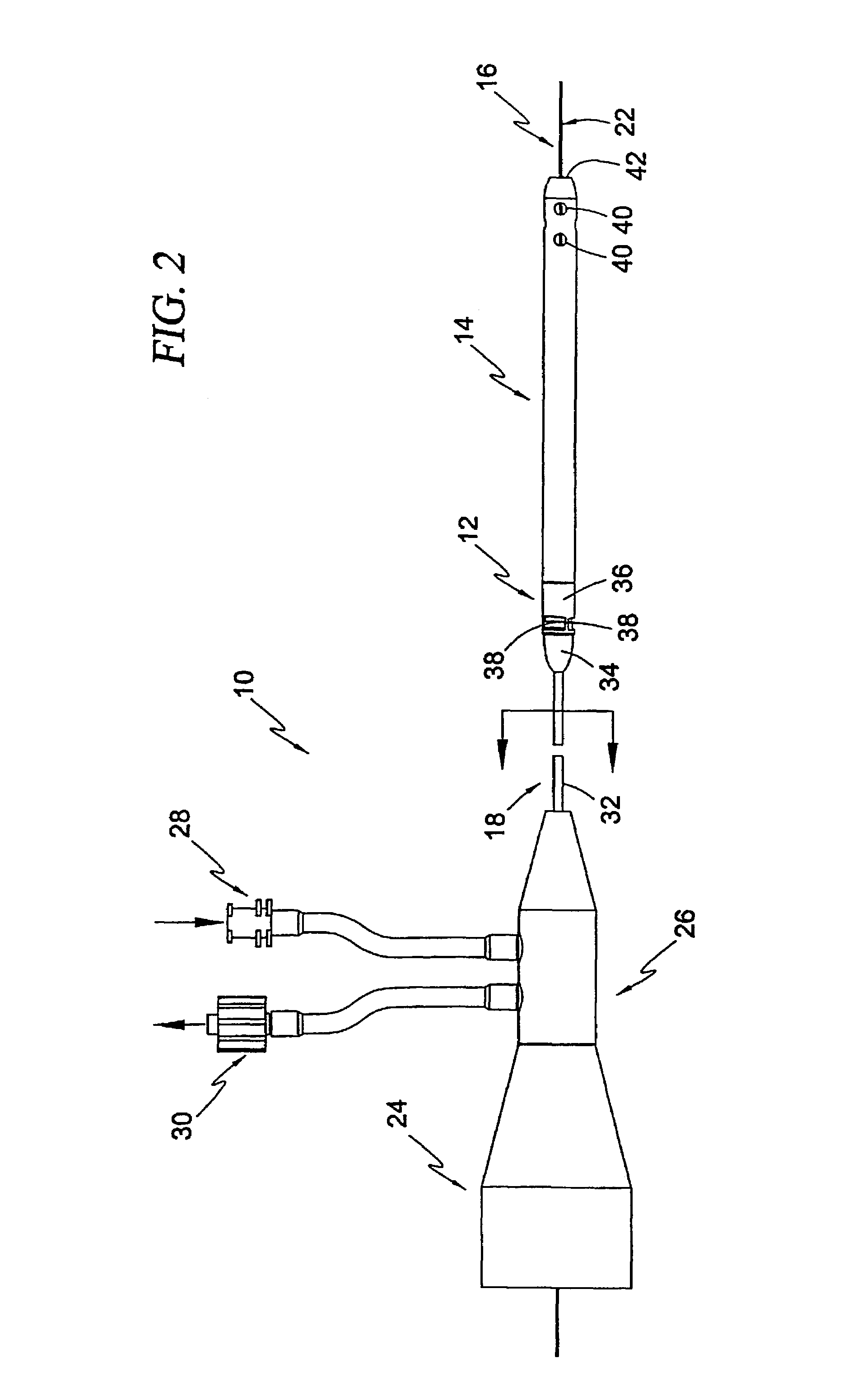
[0057]The present invention involves an intravascular pump system for use in a number of broad ranging applications involving the augmentation of blood flow within the circulatory system of a patient. As will be described below, the intravascular blood pump system of the prese...


PUM


Abstract

An improved intravascular blood pump system (10) and related methods involving the broad inventive concept of equipping the intravascular blood pump (12) with guiding features such that the intravascular blood pump can be selectively positioned at a predetermined location within the circulatory system of a patient.

Description

RELATED APPLICATIONS[0001]This application is a 371 of PCT / US00 / 24515 filed 1 Sep. 2000, which claims the benefit of provisional U.S. patent application Ser. No. 60 / 152,249, filed 3 Sep. 1999.FIELD OF THE INVENTION[0002]The present invention relates generally to blood pumps and, more particularly, to an improved intra-vascular blood pump having a guide mechanism which provides the ability to selectively guide the intravascular pump to a desired location within a patient's circulatory system.DESCRIPTION OF RELATED ART[0003]Over the years, various types of blood pumps have been developed for the purpose of augmenting or replacing the blood pumping action of damaged or diseased hearts. Blood pumps are commonly used in three situations: (1) for acute support during cardio-pulmonary operations; (2) for short-term support while awaiting recovery of the heart from surgery; or (3) as a bridge to keep a patient alive while awaiting heart transplantation. The pumps may be designed to provide ...

Claims


Application Information

Patent Timeline
Patent Type & Authority Patents(United States)
IPC IPC(8): A61M37/00A61M1/10A61M60/13A61M60/221A61M60/237A61M60/414A61M60/523A61M60/531A61M60/825A61M60/827A61M60/857A61M60/865
CPCA61M1/101A61M1/102A61M25/09A61M1/125A61M1/1029A61M1/1086A61M1/1034Y10S415/90A61M60/829A61M60/857A61M60/414A61M60/148A61M60/827A61M60/531A61M60/221A61M60/865A61M60/237A61M60/13A61M60/523A61M60/825A61M2025/0183A61M2025/0177A61M60/422A61M60/894A61M2205/3348
Inventor ABOUL-HOSN, WALID NKANZ, WILLIAM RBAKER, BRUCE
Owner MAQUET CARDIOVASCULAR LLC
Why Eureka
Try Eureka