Chemical detection sensor system

a sensor system and chemical detection technology, applied in the direction of optical radiation measurement, instruments, spectrometry/spectrophotometry/monochromators, etc., can solve the problem that the analysis of sensors generally requires bulky equipmen

Inactive Publication Date: 2006-04-04
NAVY SEC OF THE UNITED STATES
View PDF24 Cites 156 Cited by
  • Summary
  • Abstract
  • Description
  • Claims
  • Application Information

AI Technical Summary

Problems solved by technology

SERS analysis generally requires bulky equipment and typically is performed in a laboratory setting.

Method used


Image

  • Chemical detection sensor system
  • Chemical detection sensor system
  • Chemical detection sensor system

Examples


Embodiment Construction

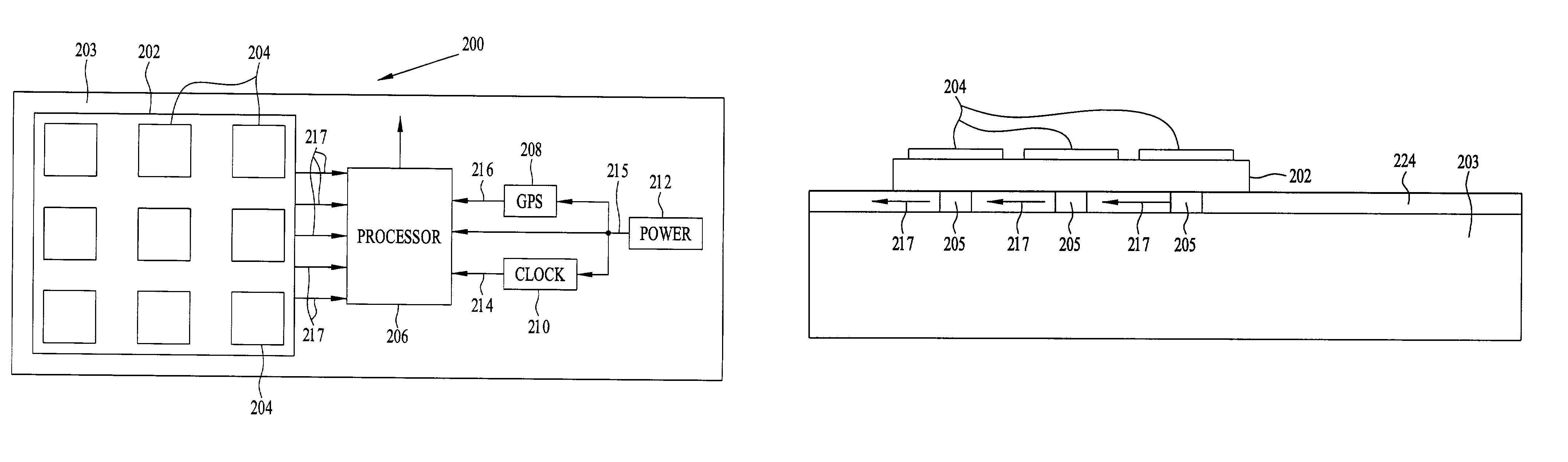
[0027]An embodiment of a chemical detection sensor system includes multiple SERS chemical detection sensors that may be configured into an array. Each chemical detection sensor of the array is designed to react with a specific class of compounds and consists of a thiol-coated, SERS-active substrate. Thiol coatings are chosen that will chemically bond to an analyte that one is interested in detecting. Once an analyte binds to the thiol coating, the analyte may be identified and quantified by its characteristic Raman emissions. Thus, an array of SERS chemical detection sensors may be designed to detect one or more different classes of chemicals or analytes, depending upon the specific thiol coating employed.

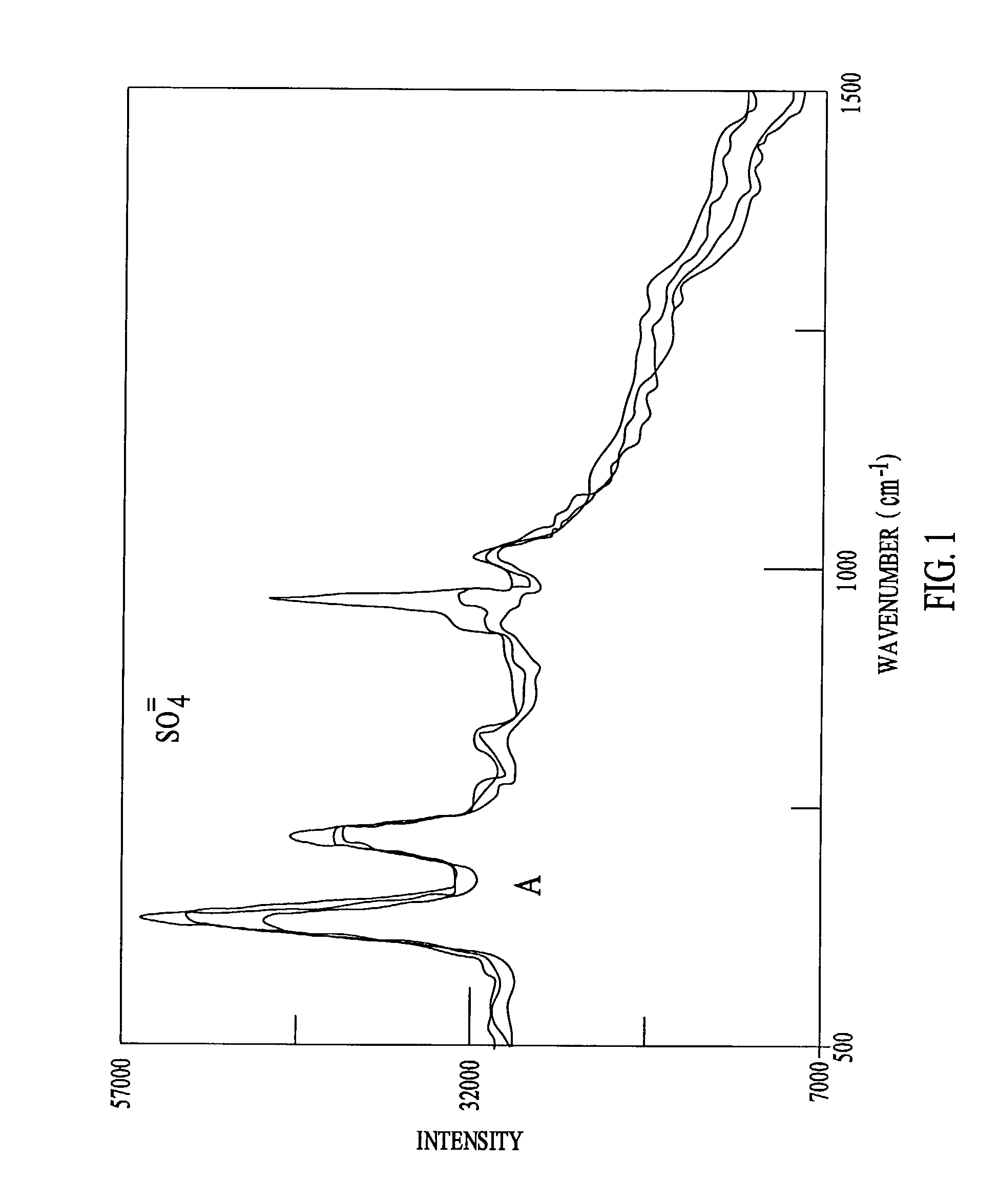
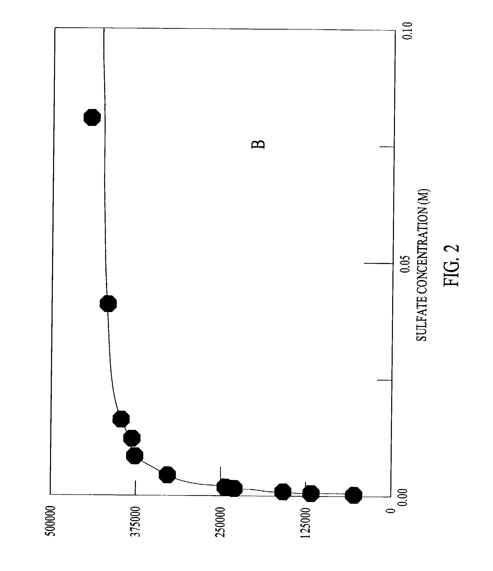
[0028]An example of an expected spectral response is shown in FIG. 1, which shows SERS spectra of sulfate interaction with a cysteamine coated chemical detection sensor. Cysteamine has a quaternary ammonium group that forms an ion pair with sulfate ion. In the example described her...


PUM

PropertyMeasurementUnit
surface roughnessaaaaaaaaaa
peak to valley depthaaaaaaaaaa
angleaaaaaaaaaa

Abstract

A chemical detection sensor system comprises a support structure; multiple SERS chemical detection sensors supported by the support structure; multiple chemical reaction sensors, wherein each of the chemical reaction sensors is disposed for undergoing a state change in response to an occurrence of a chemical reaction at one of the SERS chemical detection sensors; a processor supported by the support structure for recording data representing occurrence of a chemical reaction at any of the chemical detection sensors in response to sensing the state change; and a power source for energizing the processor.

Description

BACKGROUND OF THE INVENTION[0001]In the 1970s, it was discovered that Raman scattering of analyte molecules, upon irradiation with optical energy, can be enhanced as much as 106 to 107 when the molecules are adsorbed on noble metals such as silver, copper, and gold. This phenomenon is known as surface enhanced Raman spectroscopy (SERS). A SERS structure generally includes a metal layer formed on a substrate and is used to detect the presence of an analyte by examining the emissions from the substrate when irradiated with optical energy. SERS emissions, or spectra, have been used to detect and identify trace organics and as a detection method in gas chromatography, liquid chromatography, and thin layer chromatography. Electro chemical SERS and SERS of chemically modified surfaces have been used to detect aromatic compounds and chlorinated hydrocarbons and other organic contaminants of environmental concern in the ppb to ppm range. SERS analysis generally requires bulky equipment and ...

Claims


Application Information

Patent Timeline
Patent Type & Authority Patents(United States)
IPC IPC(8): G01N21/01G01N27/27G01N33/00
CPCB82Y15/00G01N21/658B82Y30/00Y10T436/25875
Inventor BOSS, PAMELA
Owner NAVY SEC OF THE UNITED STATES
Why Eureka
Try Eureka