Compact fuel cell with improved fluid supply

a fuel cell and fluid supply technology, applied in the field of fuel cells, can solve the problems of difficult supply of fuel gas, water is liable to be trapped, and cannot be discharged efficiently therefrom, and achieve the effect of good power generation capability, small and simple arrangemen

Active Publication Date: 2006-04-04
HONDA MOTOR CO LTD
View PDF10 Cites 19 Cited by
  • Summary
  • Abstract
  • Description
  • Claims
  • Application Information

AI Technical Summary

Benefits of technology

[0019]It is a major object of the present invention to provide a fuel cell which is capable of supplying fluids such as reactant gases smoothly and uniformly along the surfaces of separators and of achieving a good power generating capability with a small and simple arrangement.

Problems solved by technology

If the passage grooves extend parallel to each other, then generated water tends to stay in particular passage grooves, and cannot be discharged efficiently therefrom.
Therefore, it is difficult to supply the fuel gas and the oxygen-containing gas uniformly to the surfaces of the electrodes, and generated water is liable to be trapped by and stay around the protrusions 3, etc. and cannot smoothly be discharged.
When the electrodes are not cooled sufficiently, the distribution of electric energy generated in the generating surface of the fuel cell is likely to become irregular and the durability of the fuel cell tends to be lowered due to an increase in the temperature of the ion exchange membrane.
If an increased amount of coolant is supplied to prevent the above performance reduction, then the overall fuel cell system suffers a drop in the efficiency and an increase in the pressure loss.
However, since the separator is made of dense carbon, it has low toughness, is less resistant to vibrational fracture, and has a considerably large thickness.
Therefore, fuel cells incorporating the disclosed separator cannot be reduced in overall size and weight.

Method used


Image

  • Compact fuel cell with improved fluid supply
  • Compact fuel cell with improved fluid supply
  • Compact fuel cell with improved fluid supply

Examples


first embodiment

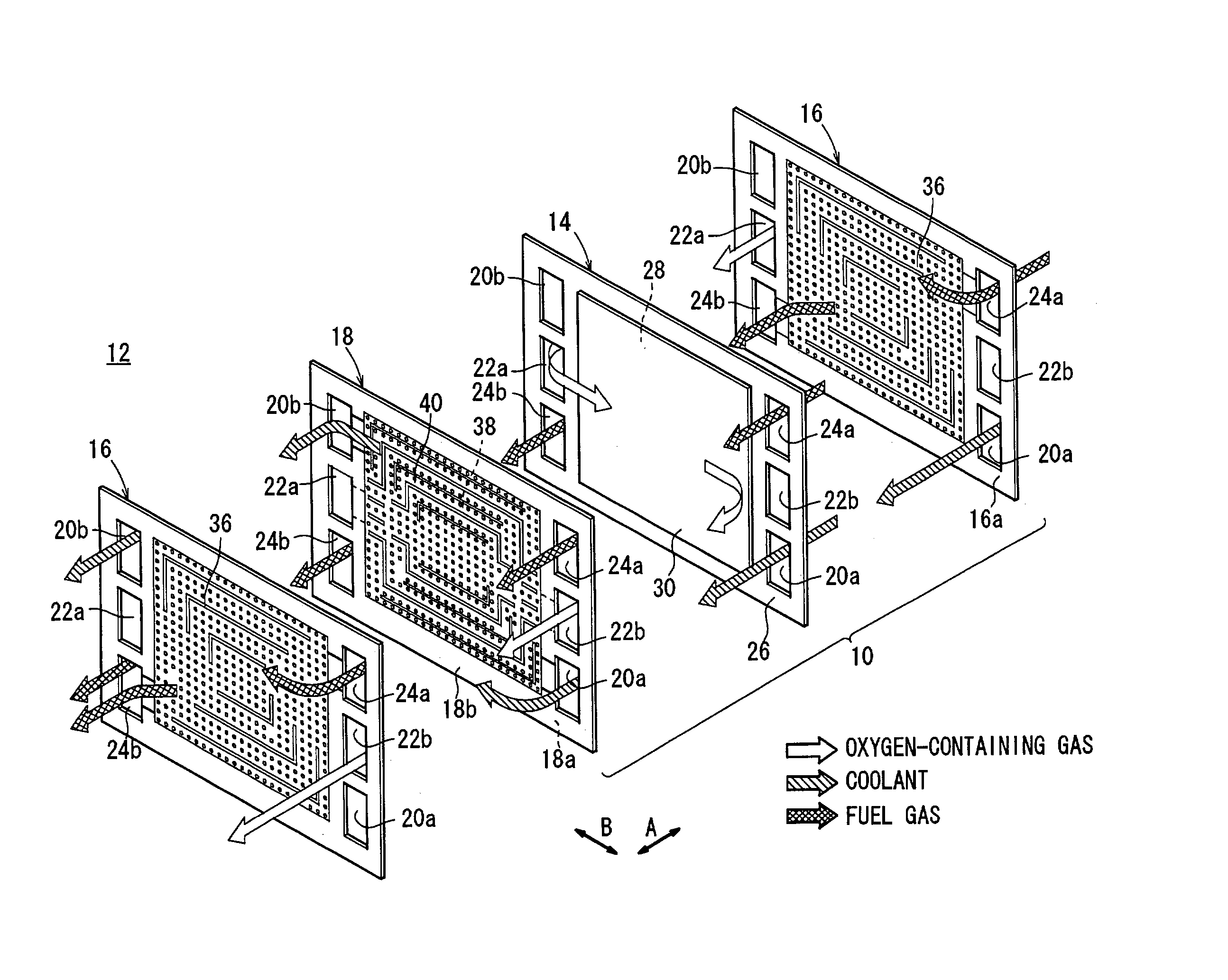
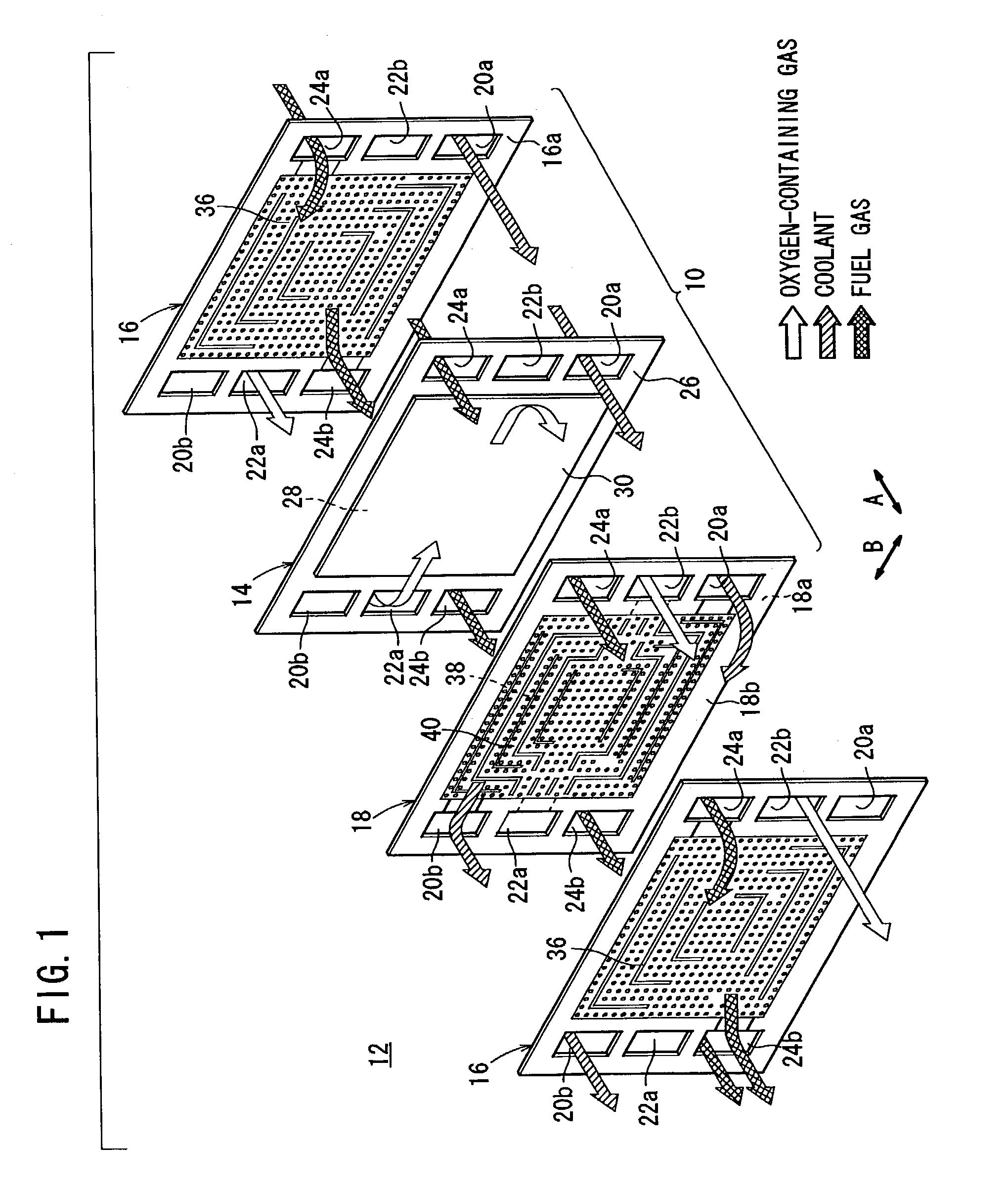
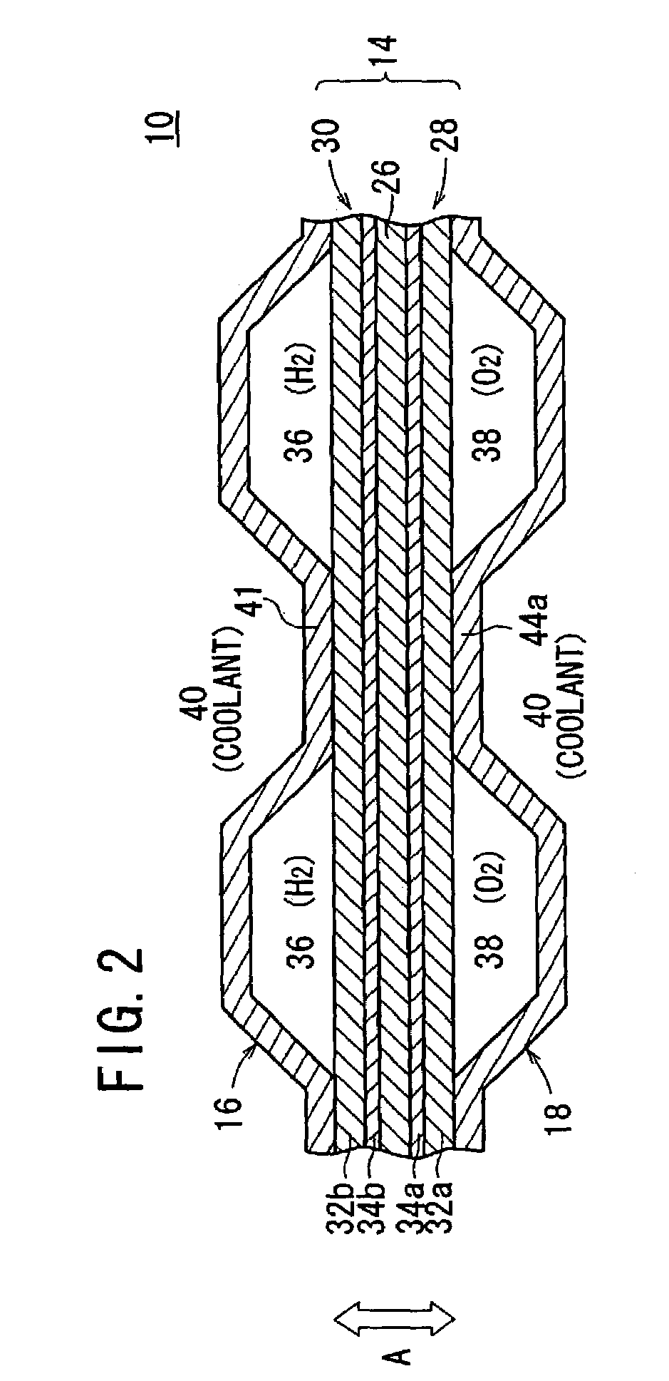
[0040]FIG. 1 shows in exploded perspective a portion of a fuel cell stack 12 incorporating a fuel cell (unit cell) 10 according to the present invention, and FIG. 2 shows the fuel cell 10 in fragmentary cross section.

[0041]As shown in FIG. 1, the fuel cell stack 12 comprises a plurality of fuel cells 10 stacked in the direction indicated by the arrow A. Each of the fuel cells 10 comprises a membrane electrode assembly (electrolyte electrode assembly) 14 and first and second separators 16, 18 sandwiching the membrane electrode assembly 14 therebetween. Each of the first and second separators 16, 18 comprises a thin metal sheet.

[0042]The membrane electrode assembly 14 and the first and second separators 16, 18 have, defined in a longitudinal end thereof (in the direction indicated by the arrow B), respective coolant outlets 20b communicating with each other in the direction indicated by the arrow A, for discharging a coolant, respective oxygen-containing gas inlets 22a communicating w...

third embodiment

[0071]FIG. 9 shows in front elevation a separator 80 of a fuel cell according to the present invention.

[0072]In FIG. 9, the separator 80 has a coolant outlet 20b and an oxygen-containing gas inlet 22a which are defined in a longitudinal end thereof, and a fuel gas inlet 24a and a coolant inlet 20a which are defined in an opposite longitudinal end thereof. The separator 80 also has an oxygen-containing gas outlet 22b and a fuel gas outlet 24b which are defined in a lower edge thereof. The separator 80 also has an oxygen-containing gas passage 82 defined on a surface 80a thereof and a coolant passage 84 defined on an opposite surface 80b thereof.

[0073]The oxygen-containing gas passage 82 has a plurality of embossed bodies 88 projecting from the surface 80a and guide ribs 90a, 90b, 90c, 90d, 90e which are provided by joining two or more embossed bodies 88. The guide ribs 90a through 90e are of respective predetermined shapes, and serve to supply an oxygen-containing gas from the oxygen...

fourth embodiment

[0075]FIG. 10 shows in front elevation a separator 100 of a fuel cell according to the present invention.

[0076]In FIG. 10, the separator 100 has an oxygen-containing gas passage 102 defined on a surface 100a thereof and a fuel gas passage 104 defined on an opposite surface 100b thereof. The oxygen-containing gas passage 102 has a plurality of embossed bodies 106 projecting from the surface 100a and guide ribs 108a, 108b, 108c, 108d which are provided by joining two or more embossed bodies 106. The guide ribs 108a through 108d are interrupted.

[0077]The fuel gas passage 104 has a plurality of embossed bodies 110 projecting from the surface 100b and guide ribs 112a, 112b, 112c, 112d, 112e which are provided by joining two or more embossed bodies 110. The guide ribs 112a through 112e are substantially L-shaped.


PUM

PropertyMeasurementUnit
areaaaaaaaaaaa
electric energyaaaaaaaaaa
temperatureaaaaaaaaaa

Abstract

A fuel cell has a membrane electrode assembly and first and second metal sheet separators. The first metal sheet separator has a fuel gas passage defined on a surface thereof. The fuel gas passage has a plurality of embossed bodies projecting from the surface which faces the membrane electrode assembly, and pairs of guide ribs provided by joining two or more of the embossed bodies.

Description

BACKGROUND OF THE INVENTION[0001]1. Field of the Invention[0002]The present invention relates to a fuel cell comprising a membrane electrode assembly having an electrolyte and electrodes disposed on respective opposite sides of the electrolyte, and a pair of metal sheet separators sandwiching the membrane electrode assembly, the separators having reactant gas passages for supplying reactant gases to the surfaces of the electrodes of the membrane electrode assembly.[0003]2. Description of the Related Art[0004]Solid polymer electrolyte fuel cells employ an ion exchange membrane (electrolyte) comprising a solid polymer ion exchange membrane (proton exchange membrane). A membrane electrode assembly comprises an anode and a cathode, each made up of an electrode catalyst and a porous carbon sheet, that are disposed in confronting relation to the opposite sides of the ion exchange membrane. The membrane electrode assembly is sandwiched between separators (bipolar plates), making up a unit ...

Claims


Application Information

Patent Timeline
Patent Type & Authority Patents(United States)
IPC IPC(8): H01M8/02H01M2/14H01M8/00H01M8/04H01M8/10H01M8/22
CPCH01M8/0258H01M8/0267H01M8/04029H01M8/04089H01M8/04059Y02E60/50H01M2008/1095H01M8/2483
Inventor ENJOJI, NAOYUKISUZUKI, MASAHARU
Owner HONDA MOTOR CO LTD
Why Eureka
Try Eureka