
Well unit for detecting cell chemotaxis and separating chemotactic cells

a cell chemotaxis and cell technology, applied in the direction of microstructural devices, liquid/fluent solid measurements, biomass after-treatment, etc., can solve the problem of unknown well unit structure, and achieve the effect of accurate and easy detection, confirmation of the effect of a chemotactic factor, and high reliability

Inactive Publication Date: 2006-04-04
ECI
View PDF29 Cites 7 Cited by
  • Summary
  • Abstract
  • Description
  • Claims
  • Application Information

AI Technical Summary

Benefits of technology

[0011]The present invention further aims at providing a well unit to be used in an apparatus for detecting the chemotaxis of cells by using cell samples in microquantities. In addition, the present invention aims at providing a well unit to be used in an apparatus for efficiently searching for a chemotactic substance and an inhibitor thereof with the use of a large number of specimens at once. The present invention furthermore aims at providing a well unit to be used in an apparatus for separating and collecting specific cells from a liquid mixture containing cells of plural types.
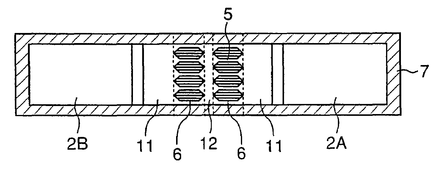
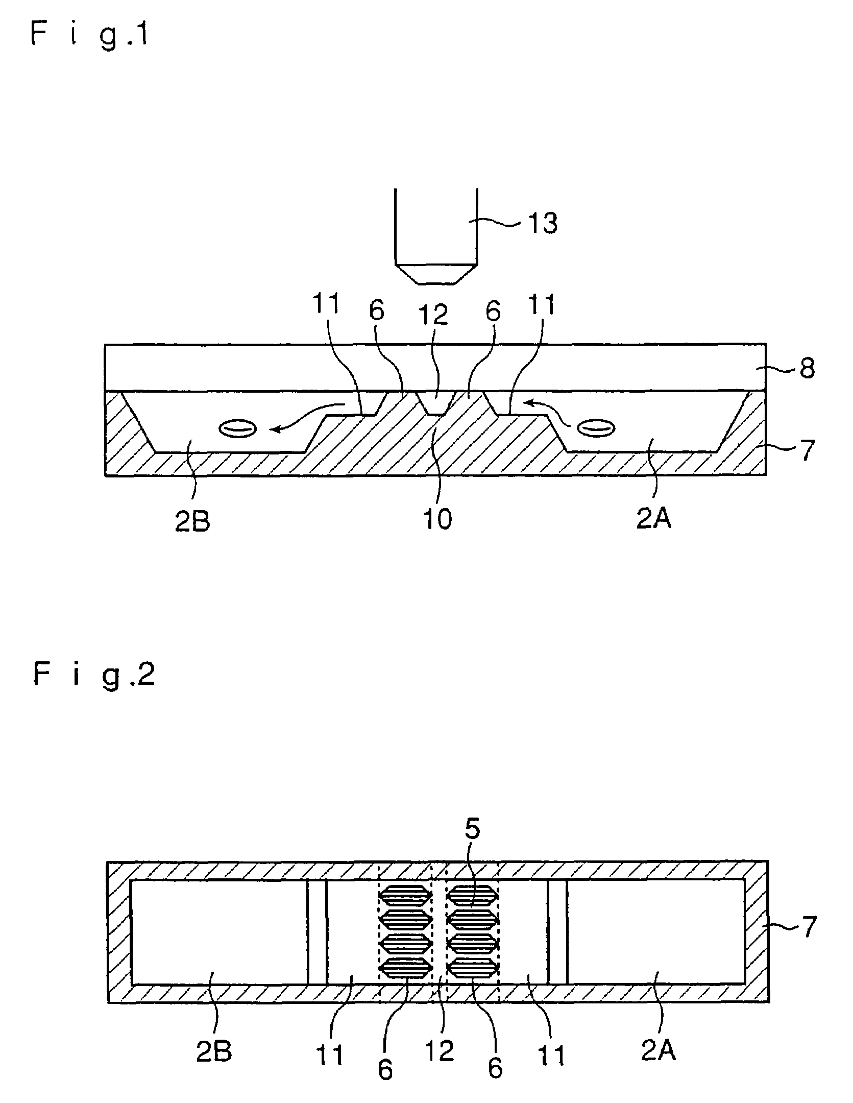
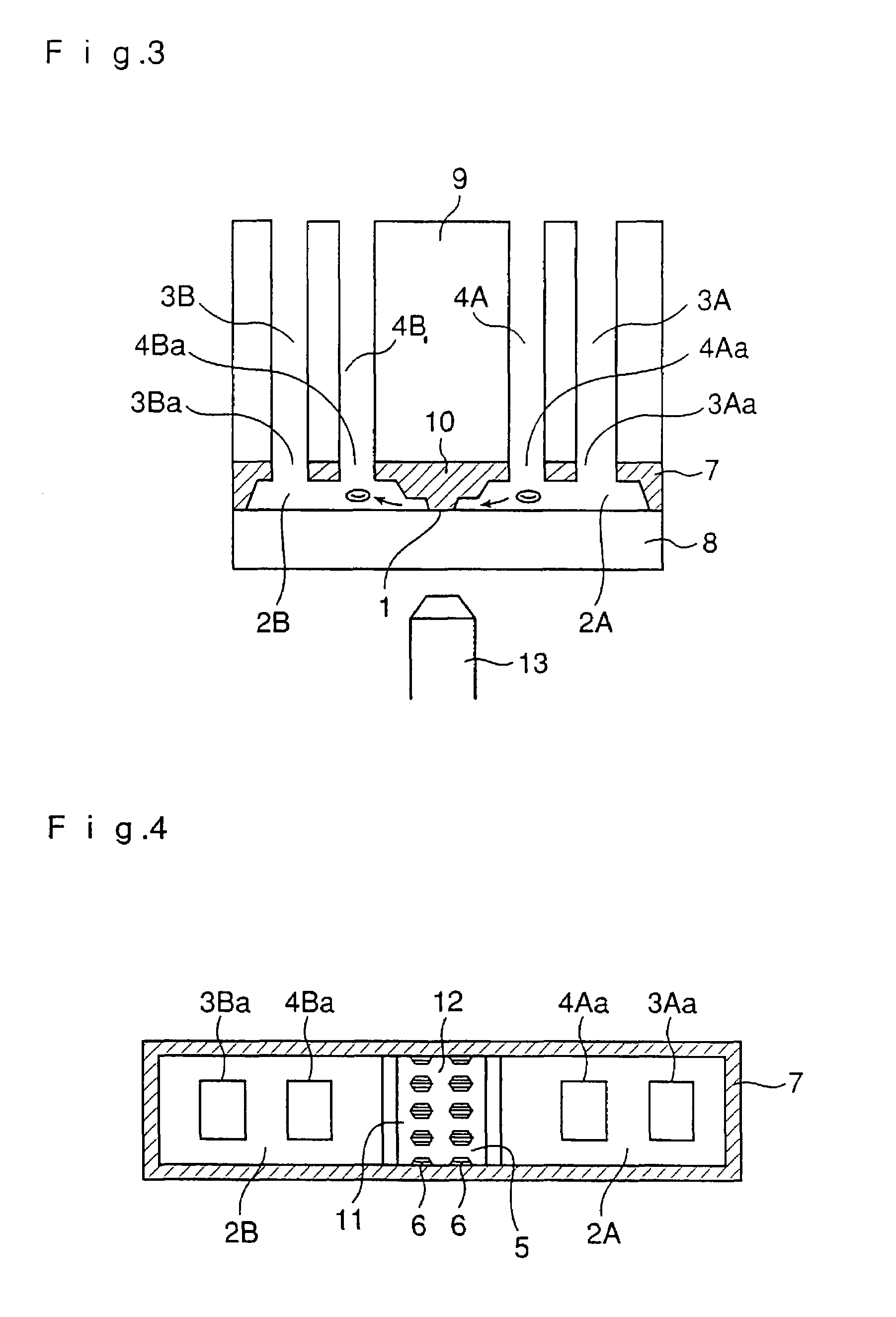
[0012]Accordingly, the present invention relates to a well unit to be used in an apparatus for detecting chemotaxis of cells and separating cells characterized in that a plural number of wells, in which a liquid sample can be held in a resting state, are connected to each other via a channel, the channel is provided with a bank, the wells are formed so as to tightly bond to a glass substrate, and, in the upper part of the bank, barriers constituting one or more grooves having a width and / or a depth fit for the diameter or deformability of cells are provided, or a plane is provided so as to give a gap having a depth fit for the diameter or deformability of cells between the plane and the glass substrate; and to the well unit as described above characterized in that a plural number of wells, in which a liquid sample can be held in a resting state, are connected to each other via a channel, the channel is provided with a bank and, in the upper part of the bank, barriers constituting one or more grooves having a width and / or a depth fit for the diameter or deformability of cells are provided. By providing the bank or by providing these barriers constituting the grooves, it is possible to easily bring together the cells held in the wells in the vicinity of the channel and align them in the flow direction of the cells before the initiation of migration. This effect can be further enhanced by employing a structure wherein a barrier for restricting the migration of the cells in the step of aligning the cells along the start line is formed orthogonally to the direction toward the opposite well, or a barrier for restricting the migration of the cells in the step of aligning the cells along the start line is formed in parallel to the array of the barriers.
[0015]In the well unit according to the present invention, it is also possible to provide a wall orthogonal to the channel in one or both of wells connected to each other via the channel to thereby restrict the amount of the liquid in the vicinity of the channel. In this well unit, moreover, a terrace may be formed to one or both of the walls formed orthogonally to the channel.

Problems solved by technology

However, there has been known no well unit structure by which the above-described situation can be established in microwells.

Method used


Image

  • Well unit for detecting cell chemotaxis and separating chemotactic cells
  • Well unit for detecting cell chemotaxis and separating chemotactic cells
  • Well unit for detecting cell chemotaxis and separating chemotactic cells

Examples


Embodiment Construction

[0085]The well unit to be used in an apparatus for detecting chemotaxis of cells and separating chemotactic cells according to the present invention has a structure wherein a plural number of wells are jointed and connected to each other via a channel. The term “well” as used herein means a container in which a cell suspension or a sample solution containing, for example, a chemotactic factor or a chemotactic factor inhibitor is held. The term “channel” means a part by which two wells are connected to each other and through which cells migrate from one well to the other well. As will be described hereinafter, the channel is provided with a bank and, in the upper part of the bank, barriers constituting one or more grooves having a width and / or a depth fit for the diameter or deformability of cells are provided, or a plane is provided so as to give a gap fit for the diameter or deformability of cells between the plane and the glass substrate. The term “deformability” of cells means th...


PUM

PropertyMeasurementUnit
diameteraaaaaaaaaa
thicknessaaaaaaaaaa
thicknessaaaaaaaaaa

Abstract

The present invention aims at providing a well unit to be used in fabricating an apparatus whereby movements of cells based on their own actions can be accurately and easily detected, in detecting the chemotaxis of cells due to a chemotactic factor or the inhibition of the chemotaxis of cells by an inhibitor.Accordingly, the present invention provides a well unit to be used in an apparatus for detecting chemotaxis of cells and separating cells characterized in that a plural number of wells, in which a liquid sample can be held in a resting state, are connected to each other via a channel, the channel is provided with a bank, and, in the upper part of the bank, barriers constituting one or more grooves having a width and / or a depth fit for the diameter or deformability of cells are provided or a plane is provided so as to give a gap having a depth fit for the diameter or deformability of cells between the plane and the glass substrate.

Description

[0001]This application is a national phase under 35 U.S.C. § 371 of PCT International Application No. PCT / JP01 / 10683 which has an International filing date of Dec. 6, 2001, which designates the United States of America.TECHNICAL FIELD[0002]This invention relates to a well unit to be used in an apparatus for judging whether or not cells can migrate in a definite direction by their own actions, observing the state of cells migrating in a definite direction by their own actions, or counting cells having migrated in a definite direction by their own actions (i.e., an apparatus for detecting chemotaxis of cells) and an apparatus for separating cells based on the selective migration of cells in a definite direction by their own actions.BACKGROUND ART[0003]It has been a practice to use a Boyden chamber as an apparatus for detecting chemotaxis of cells in vitro. This apparatus has a structure partitioned into an upper chamber and a lower chamber by a filter having pores (diameter: 3 to 8 μm...

Claims


Application Information

Patent Timeline
Patent Type & Authority Patents(United States)
IPC IPC(8): C12M1/34B01L3/00B81B1/00B81C99/00G01N15/14G01N33/50G01N33/53
CPCB01L3/5027C12M41/46G01N33/5005G01N33/5302G01N15/1456B01L3/502761B01L2300/0861B01L2400/086G01N2015/1486G01N2015/1493C12M1/34G01N33/48
Inventor KANEGASAKI, SHIROKIKUCHIKIKUCHI, HIROKO
Owner ECI
Learn More