Monochromator and scanning electron microscope using the same

Inactive Publication Date: 2006-04-04
HITACHI HIGH-TECH CORP
View PDF17 Cites 15 Cited by
  • Summary
  • Abstract
  • Description
  • Claims
  • Application Information

AI Technical Summary

Benefits of technology

[0023]An object of the present invention is therefore to provide a monochromator and a scanning electron microscope using that

Problems solved by technology

The energy filter using a magnetic field to perform filtering had the problem that when attempting to obtain secondary beam convergence by lateral irradiation onto the magnetic pole surface, secondary chromatic aberrations occurred and the scanning beam could not be sufficiently narrowed, resulting in poor resolution.
When used as a monochromator however, these cause distortions in the electrical field d

Method used


Image

  • Monochromator and scanning electron microscope using the same
  • Monochromator and scanning electron microscope using the same
  • Monochromator and scanning electron microscope using the same

Examples


first embodiment

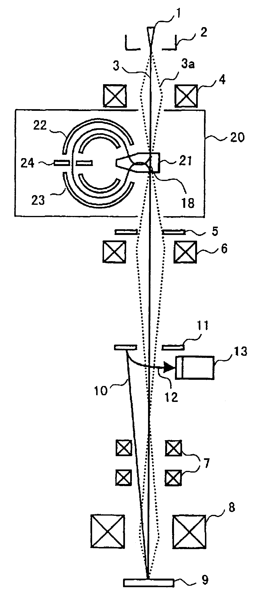
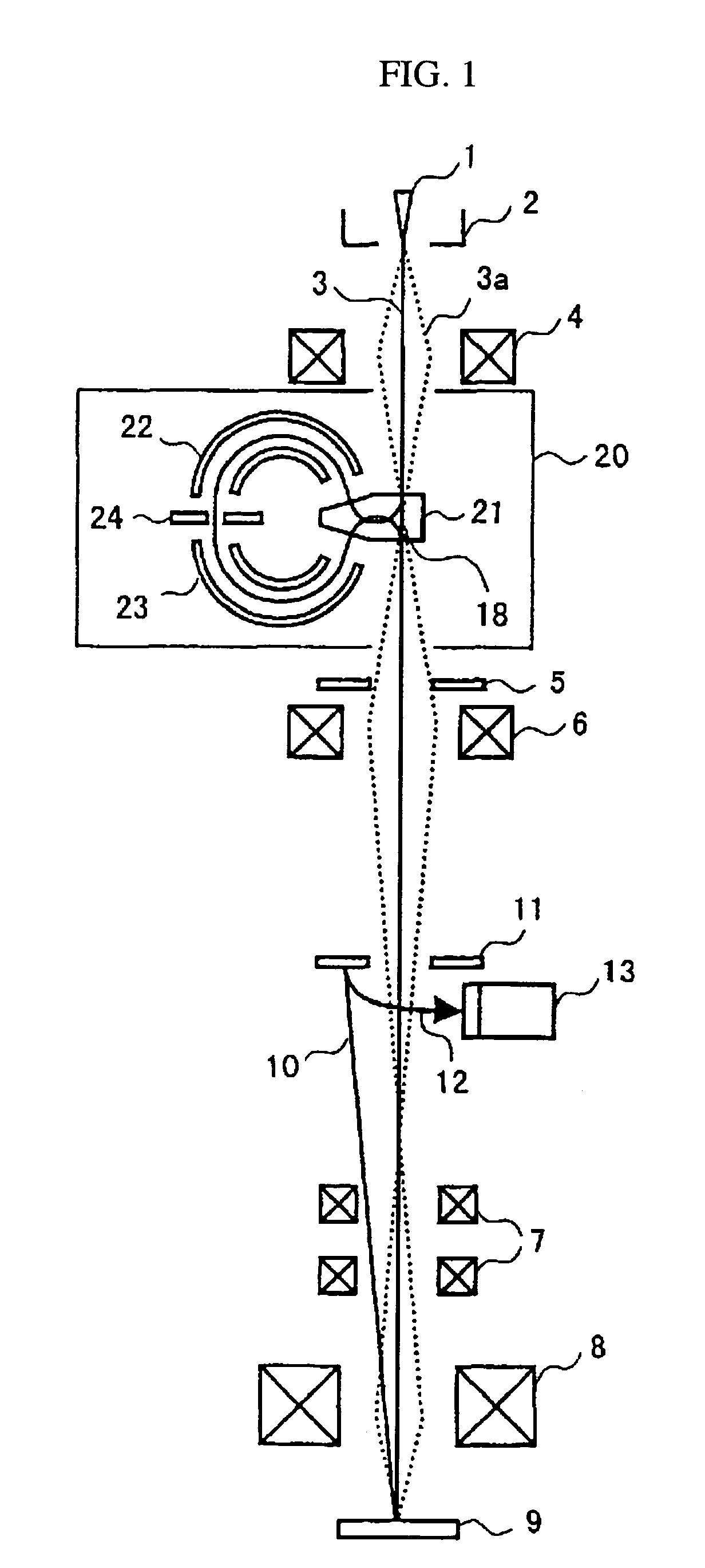
[0039]The optical system and optical system operation for the scanning electron microscope containing a monochromator of the first embodiment of the present invention is described next while referring to FIG. 1.

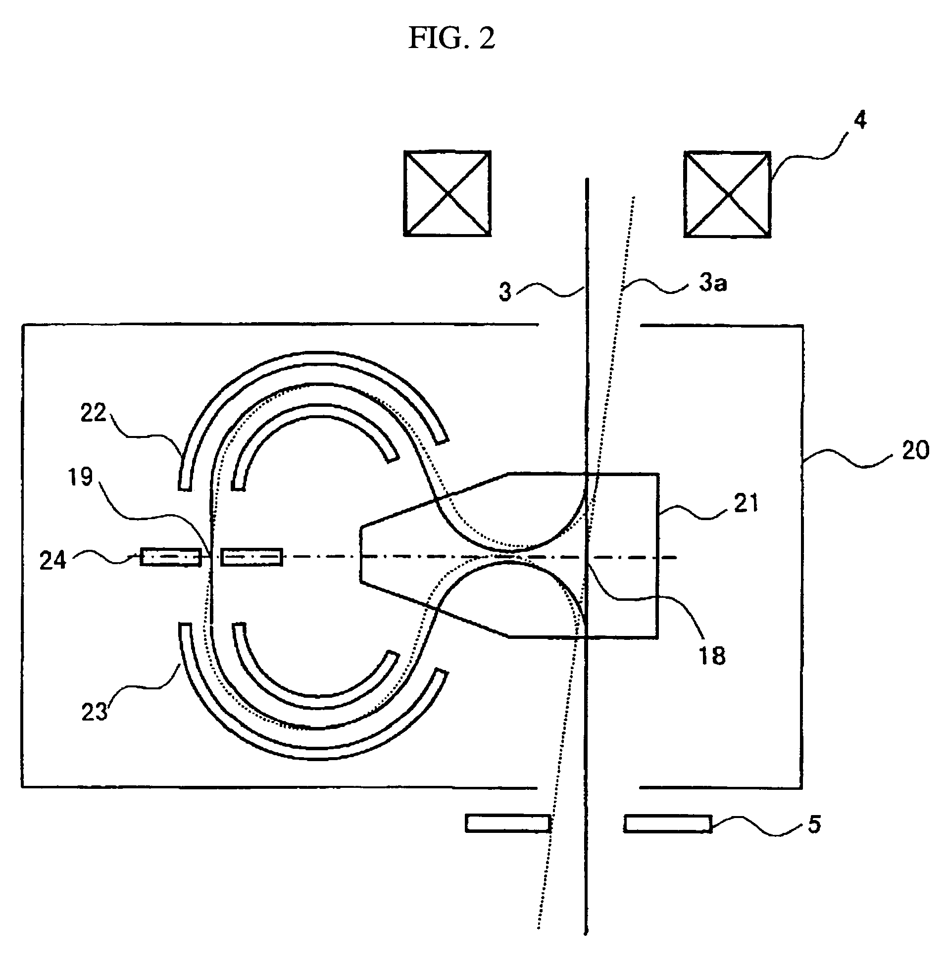
[0040]When a voltage is applied across an electron source 1 and anode electrode 2, an electron beam 3 is emitted from the electron source 1 along the linear optical axis. This electron beam 3 also includes an electron beam 3a widening to several dozen millirads, coupling the actual image of the electron source to an internal section of the monochromator 20 with a first convergence lens 4. The electron beam is then deflected in a range of 140 degrees or more and 170 degrees or less, by a magnetic field generator 21 of the prestage deflector system, and by deflecting to the same angle in the opposite direction by a first electrical field generator 22, the beam is placed in a direction parallel to the original linear optical axis, focused at the slits 24 position in the x direct...

second embodiment

[0076]The second embodiment of the invention is described next. The energy dispersion trajectory 3d is shown in FIG. 11. The energy dispersion trajectory is emitted at the point in time that the first sectorial magnetic field formed by the magnetic field generator 21 is irradiated. This becomes uniform after passing the first sectorial electrical field formed by the first electrical field generator 22 and passes through the beam restrictor 24. After then passing along the mirror-symmetrical trajectory, the energy dispersion diminishes and becomes completely zero at the point of emission from the sectorial magnetic field formed by the magnetic field generator 21. Even after emission, the energy dispersion of the electron beam 3d remains unchanged at zero. Summing the above, since the energy dispersion along the linear optical axis is always zero, the beam is subjected to point convergence and triple convergence from energy non-dispersion regardless of the point convergence position. ...


PUM


Abstract

An invention providing a scanning electron microscope composed of a monochromator capable of high resolution, monochromatizing the energy and reducing chromatic aberrations without significantly lowering the electrical current strength of the primary electron beam. A scanning electron microscope is installed with a pair of sectorial magnetic and electrical fields having opposite deflection directions to focus the electron beam and then limit the energy width by means of slits, and another pair of sectorial magnetic and electrical fields of the same shape is installed at a position forming a symmetrical mirror versus the surface containing the slits. This structure acts to cancel out energy dispersion at the object point and symmetrical mirror positions, and by spatially contracting the point-converged spot beam with a converging lens system, improves the image resolution of the scanning electron microscope.

Description

FIELD OF THE INVENTION[0001]The present invention relates to a monochromator for making the energy of an electron beam monochrome and a scanning electron microscope having the same.BACKGROUND OF THE INVENTION[0002]In recent years, the scanning electron microscope in many cases utilizes a low acceleration energy within a few kilovolts to prevent the electron beam from generating an electrostatic charge on the semiconductor sample. In these types of low acceleration SEM (scanning electron microscopes), the characteristic energy width of the electron source for the acceleration energy becomes relatively large so chromatic aberrations prevent obtaining an electron beam with a sufficiently small spot.[0003]To solve this problem, technology utilizing an energy filter to selectively allow only electrons in the desired energy range to pass was disclosed in patent documents 1 through 5.[0004]Patent document 1 discloses technology for reducing the chromatic aberrations by installing a magneti...

Claims


Application Information

Patent Timeline
IPC IPC(8): H01J37/05H01J37/09H01J37/153H01J37/26H01J37/28H01J49/46
CPCH01J37/05H01J37/28H01J37/153
Inventor OSE, YOICHITAYA, SHUNROKUTODOKORO, HIDEOOTAKA, TADASHISATO, MITSUGUEZUMI, MAKOTO
Owner HITACHI HIGH-TECH CORP
Why Eureka
Try Eureka