
Module, system and method for testing a phase locked loop

a phase lock and module technology, applied in the direction of noise figure or signal-to-noise ratio measurement, frequency to phase shift conversion, instruments, etc., can solve the problems of no calibration mechanism that allows the determination of the jitter value, no cycle-to-cycle jitter measurement, and minimum one analog part required

Inactive Publication Date: 2006-04-04
NORTH STAR INNOVATIONS
View PDF13 Cites 15 Cited by
  • Summary
  • Abstract
  • Description
  • Claims
  • Application Information

AI Technical Summary

Benefits of technology

[0014]In this way a module, system and method for testing a phase locked loop are provided in which cycle-to-cycle and phase jitter measurements may be made. A calibration mechanism is provided allowing a process evaluation to be made and which allows the jitter data to be provided in a few seconds. The fully digital design facilitates easy manufacture and readily retargeting of the module to diverse applications and processes.

Problems solved by technology

However, this approach has the disadvantages that at least one analogue part is required.
Furthermore, no cycle-to-cycle jitter measurement is performed, and there is no calibration mechanism that allows the determination of the jitter value.

Method used


Image

  • Module, system and method for testing a phase locked loop
  • Module, system and method for testing a phase locked loop
  • Module, system and method for testing a phase locked loop

Examples


Embodiment Construction

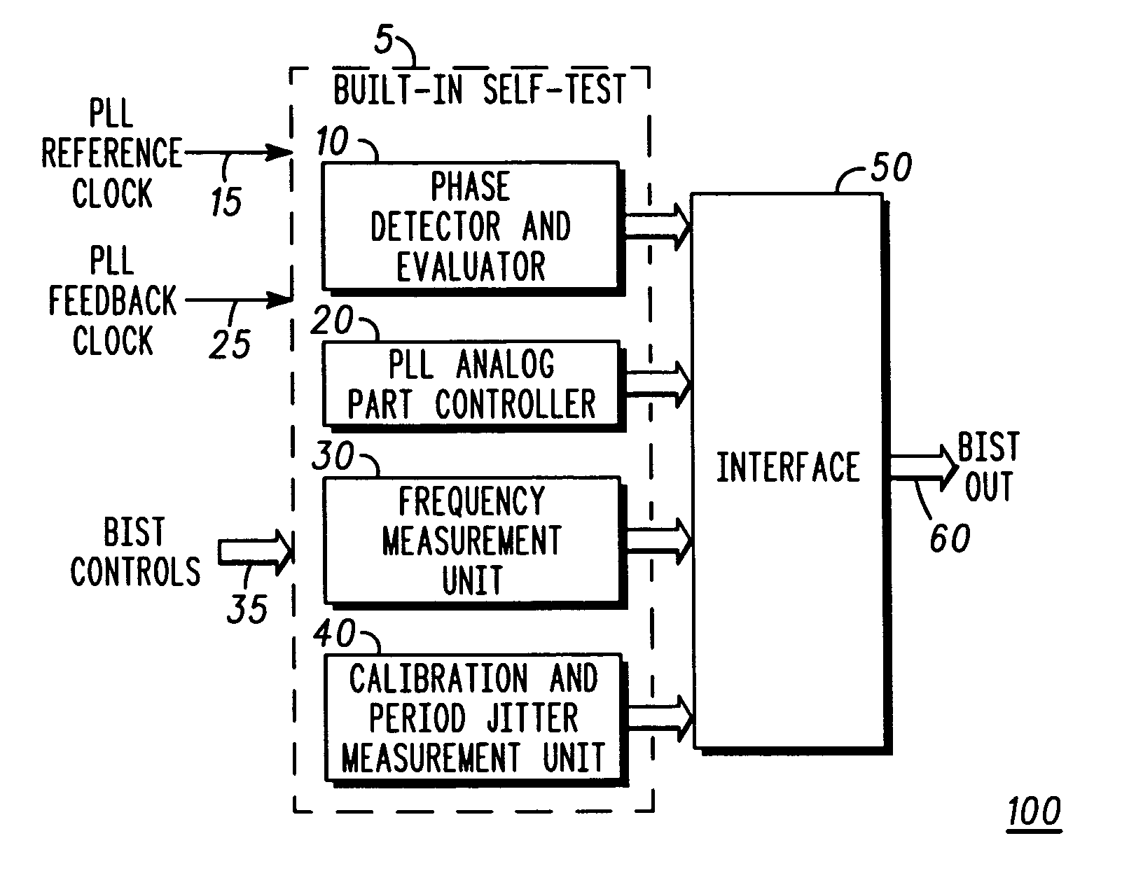
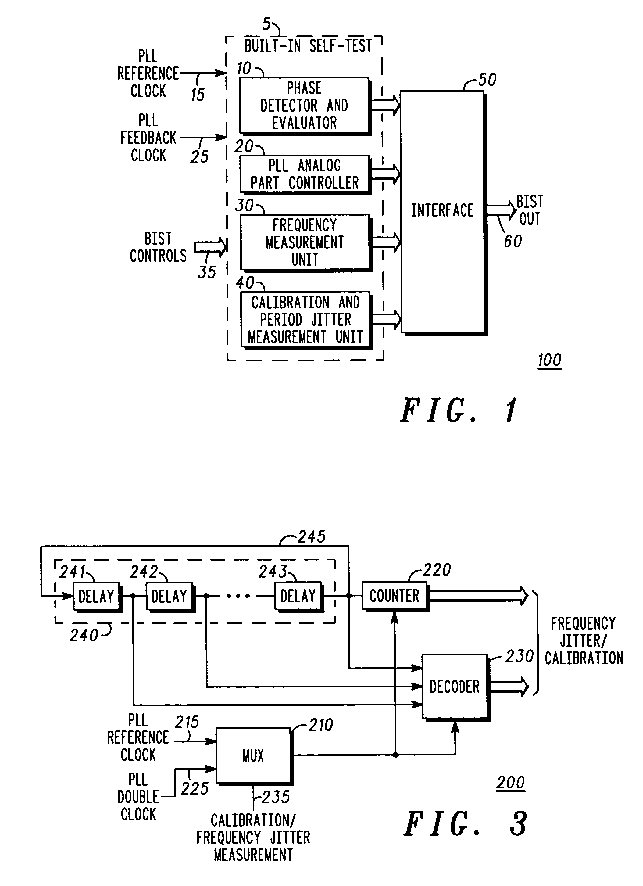
[0020]Referring to FIG. 1 of the drawings, there is shown a Built-In Self-Test (BIST) module 5 of a PLL circuit, which may be ‘built-in’ (i.e. embedded in) an integrated circuit having other modules or components. The module 5 is entirely fabricated as a digital design, and is ‘self-test’ because it includes embedded test units to be described below.

[0021]The module 5 comprises a phase detector / evaluator 10, a PLL analogue part control unit 20, an frequency measurement unit 30 and a calibration and period jitter measurement unit 40. The BIST 5 is arranged to receive a PLL reference clock signal 15, a PLL feedback clock signal 25 and a number of BIST control signals 35. Each element of the BIST 5 is coupled to an interface 50 from which output signals 60 are provided.

[0022]The DPLL BIST communicates with the DPLL module and includes the interface that should be defined by each project for dumping its data out. There are at least two interface possibilities: forwarding data to the IOs...


PUM


Abstract

A digital test module (5) is provided for testing a phase locked loop circuit. The module (5) includes phase detection circuitry (10) for performing phase measurements of the phase locked loop circuit and analog test circuitry (20) for testing at least one analog element of the phase locked loop circuit. Frequency measurement circuitry (30) is provided for performing frequency measurements of the phase locked loop circuit, as is circuitry (40) for performing calibration and jitter measurements. In this way cycle-to-cycle and phase jitter measurements may be made. A calibration mechanism is provided allowing a process evaluation to be made and which allows the jitter data to be provided in a few seconds. The fully digital design facilitates easy manufacture and ready retargeting of the module to diverse applications and processes.

Description

FIELD OF THE INVENTION[0001]This invention relates to the testing of phase locked loops, and particularly but not exclusively to such testing of phase locked loops in devices such as network communication systems, wireless subscriber units, wireless infrastructure and the like.BACKGROUND OF THE INVENTION[0002]Phase Locked Loops (PLLs), are used in a high proportion of current electronic devices, including mobile telephones and other communication equipment. In such devices there is an increasing move for reliability, cost and performance reasons to replace analogue components wherever possible with digital equivalent circuitry.[0003]It is important that any phase ‘jitter’, (i.e. a spurious phase discrepancy) occurring in PLLs is identified and compensated for.[0004]In the field of this invention it is known to perform only a frequency count of a PLL, and to perform a “pass / fail” test for only phase jitter, the output of the PLL not being calibrated internally.[0005]However, this app...

Claims


Application Information

Patent Timeline
Patent Type & Authority Patents(United States)
IPC IPC(8): G01R23/12H03D3/24G01R25/00G01R29/26
CPCG01R29/26G01R25/00
Inventor ROSENBAUM, YAIRSOFER, SERGEYYEHUSHUA, EMIL
Owner NORTH STAR INNOVATIONS
Learn More