Method and apparatus for magnetic resonance imaging and spectroscopy using microstrip transmission line coils

a transmission line coil and magnetic resonance imaging technology, applied in the field of magnetic resonance imaging (mri), can solve the problems of reducing the quality factor or q factor of the coil, the volume inside the main magnet of many mri systems is relatively small, and the coil is not easy to operate in addition to the patient, so as to achieve low cost components, compact design, and easy manufacturing

Inactive Publication Date: 2006-04-04
RGT UNIV OF MINNESOTA
View PDF41 Cites 82 Cited by
  • Summary
  • Abstract
  • Description
  • Claims
  • Application Information

AI Technical Summary

Benefits of technology

[0006]According to certain example embodiments of the invention there are provided a MRI coil formed of microstrip transmission line. According to various embodiments of the invention, MRI coils according the present invention are easy to manufacture with relatively low cost components, and compact in design. In addition, the coil's distributed element design provides for operation at relatively high quality factors and frequencies and in high field (4 Tesla or more) environments. Further, microstrip coils according to the present invention exhibit relatively low radiation losses and require no RF shielding. As a result of not requiring RF shielding, the coils may be of compact size while having high operating frequencies for high field MR studies, thus saving space in the MRI machine. Further, the methods and apparatus of the present invention are not just good for high frequency MR studies, but also good for low frequency cases.

Problems solved by technology

Further, the operating volume inside the main magnet of many MRI systems is relatively small, often just large enough for a patient's head or body.
As a result, there is typically little space available for a coil in addition to the patient.
In high fields (3 Tesla and beyond), due to the high Larmour frequencies required, radiation losses of RF coils become significant which decreases a coil's quality factor or Q factor, and a low Q factor can result in low signal-to-noise ratio (SNR) in MRI procedures.
The RF shielding, however, usually makes the physical size of RF coil much larger, which as noted above is not desired in the MR studies, especially in the case of high field operations.

Method used


Image

  • Method and apparatus for magnetic resonance imaging and spectroscopy using microstrip transmission line coils
  • Method and apparatus for magnetic resonance imaging and spectroscopy using microstrip transmission line coils
  • Method and apparatus for magnetic resonance imaging and spectroscopy using microstrip transmission line coils

Examples


first embodiment

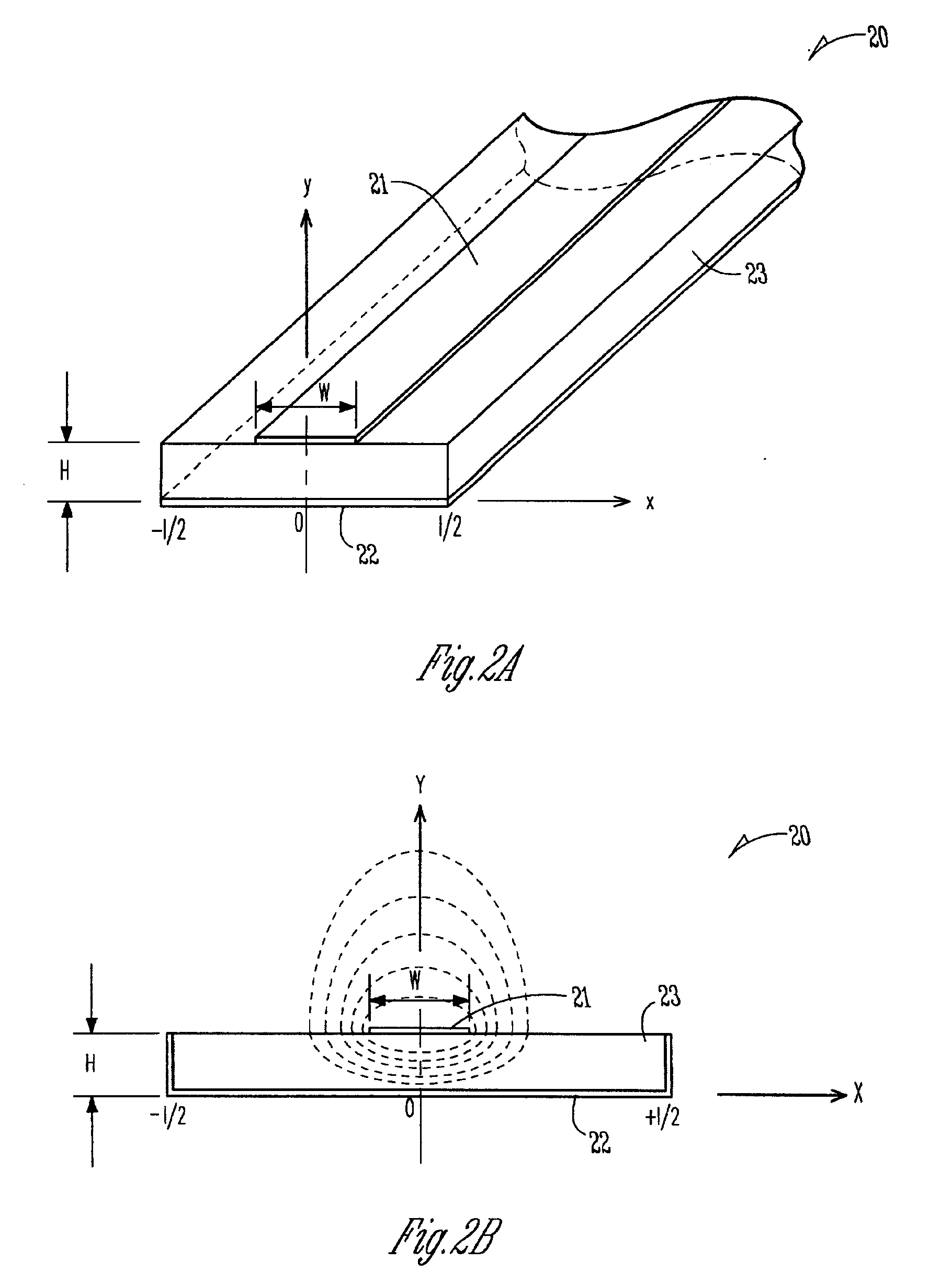
[0021]According to the apparatus of the invention, as illustrated in FIGS. 2C and 2D, there is provided a single turn MRI imaging or spectroscopy MTL coil 23 constructed using at least one microstrip transmission line. The microstrip transmission line coil, according to one example design, is formed of a strip conductor 24, a ground plane 25 and a substrate 26 made of a dielectric material that may be air, a vacuum, a single or multilayer low loss dielectric sheets such as Teflon or Duroid materials, or liquid Helium or Nitrogen. According to one example embodiment, such coil is 9 cm×9 cm, has a substrate 26 that is 5-7 mm, uses copper foil 36 microns in thickness (for example an adhesive-backed copper tape such as is available from 3M Corporation of St. Paul, Minn.) for the strip conductors and ground plane, and has a resonant frequency of 300 MHz. According to one example embodiment, the MRI signal intensity is proportional to H when H1 penetration in air. If H is too small, or W / ...

embodiment 60

[0025]In still another example embodiment illustrated in FIGS. 5A and 5B, the MTL coil 50 includes a bisected ground plane 52. In this configuration, tuning of the resonance frequency is accomplished by adjusting displacement 54 of at least one of the ground planes. As illustrated in FIG. 6, in yet another embodiment 60, PIN diodes 64 are positioned in the gap 66 of the bisected ground planes 62, and used to detune the coil.

[0026]According to still other example embodiments of the apparatus of the invention illustrated in FIG. 7A, a MTL coil 70 is tuned by varying capacitive termination elements 72 on one end of the coil. FIG. 7B illustrates a hypothetical plot of magnetic field profile vs. capacitive termination value for a range of capacitances. As illustrated, increasing capacitive termination raises the magnetic field profile at the end of the coil at which the termination is applied. FIGS. 7C and 7D illustrate an example embodiment and field profile for tuning a MTL coil 74 by ...


PUM

PropertyMeasurementUnit
resonant frequencyaaaaaaaaaa
thicknessaaaaaaaaaa
thicknessaaaaaaaaaa

Abstract

Apparatus and method for MRI imaging using a coil constructed of microstrip transmission line (MTL coil) are disclosed. In one method, a target is positioned to be imaged within the field of a main magnetic field of a magnet resonance imaging (MRI) system, a MTL coil is positioned proximate the target, and a MRI image is obtained using the main magnet and the MTL coil. In another embodiment, the MRI coil is used for spectroscopy. MRI imaging and spectroscopy coils are formed using microstrip transmission line. These MTL coils have the advantageous property of good performance while occupying a relatively small space, thus allowing MTL coils to be used inside restricted areas more easily than some other prior art coils. In addition, the MTL coils are relatively simple to construct of inexpensive components and thus relatively inexpensive compared to other designs. Further, the MTL coils of the present invention can be readily formed in a wide variety of coil configurations, and used in a wide variety of ways. Further, while the MTL coils of the present invention work well at high field strengths and frequencies, they also work at low frequencies and in low field strengths as well.

Description

CROSS REFERENCE TO RELATED APPLICATIONS[0001]This application is a continuation of provisional application Ser. No. 60 / 239,185, filed, Oct. 9, 2000, and entitled “Microstrip Resonator RF Surface and Volume Coils and Methods for NMR Imaging and Spectroscopy at High Fields.” The entire contents of U.S. application Ser. No. 60 / 239,185 are hereby incorporated herein by reference.GOVERNMENT RIGHTS[0002]This invention was partially supported by NIH grants NS38070 (W.C.), NS39043 (W.C.), P41 RR08079 (a National Research Resource grant from NIH), Keck Foundation, National Foundation for Functional Brain Imaging and the US Department of Energy. The Government may have certain rights in the invention.TECHNICAL FIELD OF THE INVENTION[0003]This invention pertains generally to magnetic resonance imaging (MRI) and more specifically to surface and volume coils for MRI imaging and spectroscopy procedures.BACKGROUND OF THE INVENTION[0004]Surface and volume coils are used in MRI imaging or spectrosco...

Claims


Application Information

Patent Timeline
Patent Type & Authority Patents(United States)
IPC IPC(8): G01V3/00A61B5/055G01N22/00G01R33/34G01R33/341G01R33/343G01R33/345
CPCG01R33/345H01Q17/00G01R33/34007Y10T29/49073Y10T29/4902
Inventor ZHANG, XIAOLIANGUGURBIL, KAMILCHEN, WEI
Owner RGT UNIV OF MINNESOTA
Why Eureka
Try Eureka