Gain calibration device and method for differential push-pull tracking error signals

a calibration device and differential push-pull technology, applied in data recording, instruments, carrier indexing/addressing/timing/synchronisation, etc., can solve the problems of inability to obtain information during the duration of correcting spp and inability to obtain spp using the conventional method, and achieve good uniformity and stability.

Inactive Publication Date: 2006-04-04
MEDIATEK INC
View PDF4 Cites 8 Cited by
  • Summary
  • Abstract
  • Description
  • Claims
  • Application Information

AI Technical Summary

Benefits of technology

[0029]The calibration device and method of the invention can prevent the signal levels of the synthesized DPP tracking error (DPP) signals from being interfered during the deviation of the unstable optical path cause by the lens-shift of the objective lens, or the lens-tilt of the objective lens or optical disc owing to mechanism tolerance during the tracking procedure. Thus, the center position of the groove of the optical disc can be kept at the reference level of the DPP signal, and the laser spot under the track-locking servo control is assured to align with the center position of the groove. Meanwhile, in the repeated procedures of track jumping and track locking, the DPP signal levels meet the standard waveform with balanced positive and negative amplitudes. In addition, the synthesized gain (SPPG) obtained from the calibration device is free from being influenced by the factors such as the laser spot position error resulting from the tolerance of the inner mechanism of the pick-up head, and the track pitch deviations between different optical discs. Consequently, the device has good uniformity and stability and is suitable to be widely used in the industry.

Problems solved by technology

Therefore, the information cannot be obtained during the duration for correcting the SPP gain.
Accordingly, the correct gain for SPP cannot be obtained using the conventional method.

Method used


Image

  • Gain calibration device and method for differential push-pull tracking error signals
  • Gain calibration device and method for differential push-pull tracking error signals
  • Gain calibration device and method for differential push-pull tracking error signals

Examples


Embodiment Construction

[0036]The gain calibration method for the DPP tracking in the optical storage system of the present invention will be described with reference to the accompanying drawings. The embodiments to be described later are directed to the control for lens-shift movement of the objective lens, and a step response method is used as the control method.

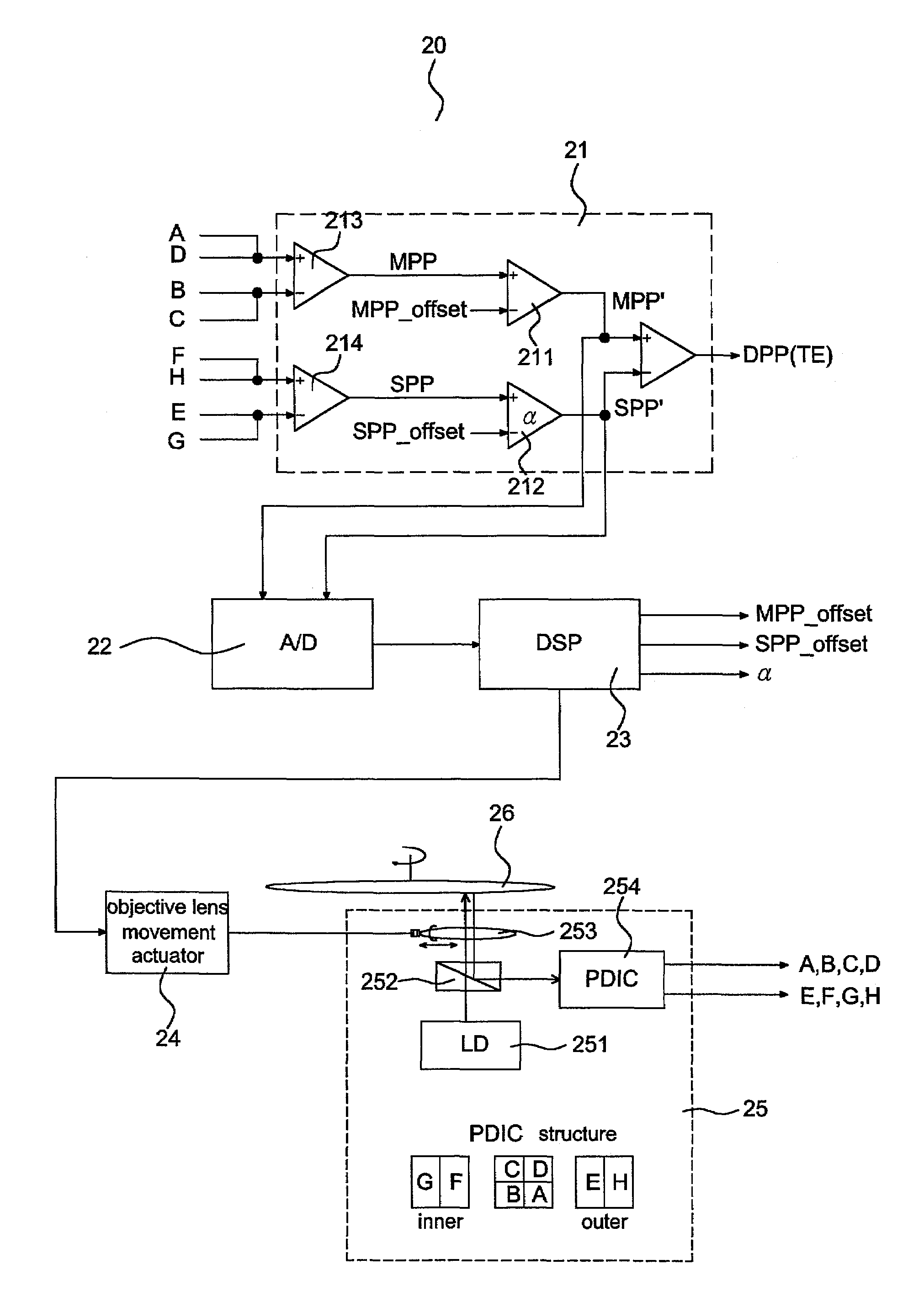
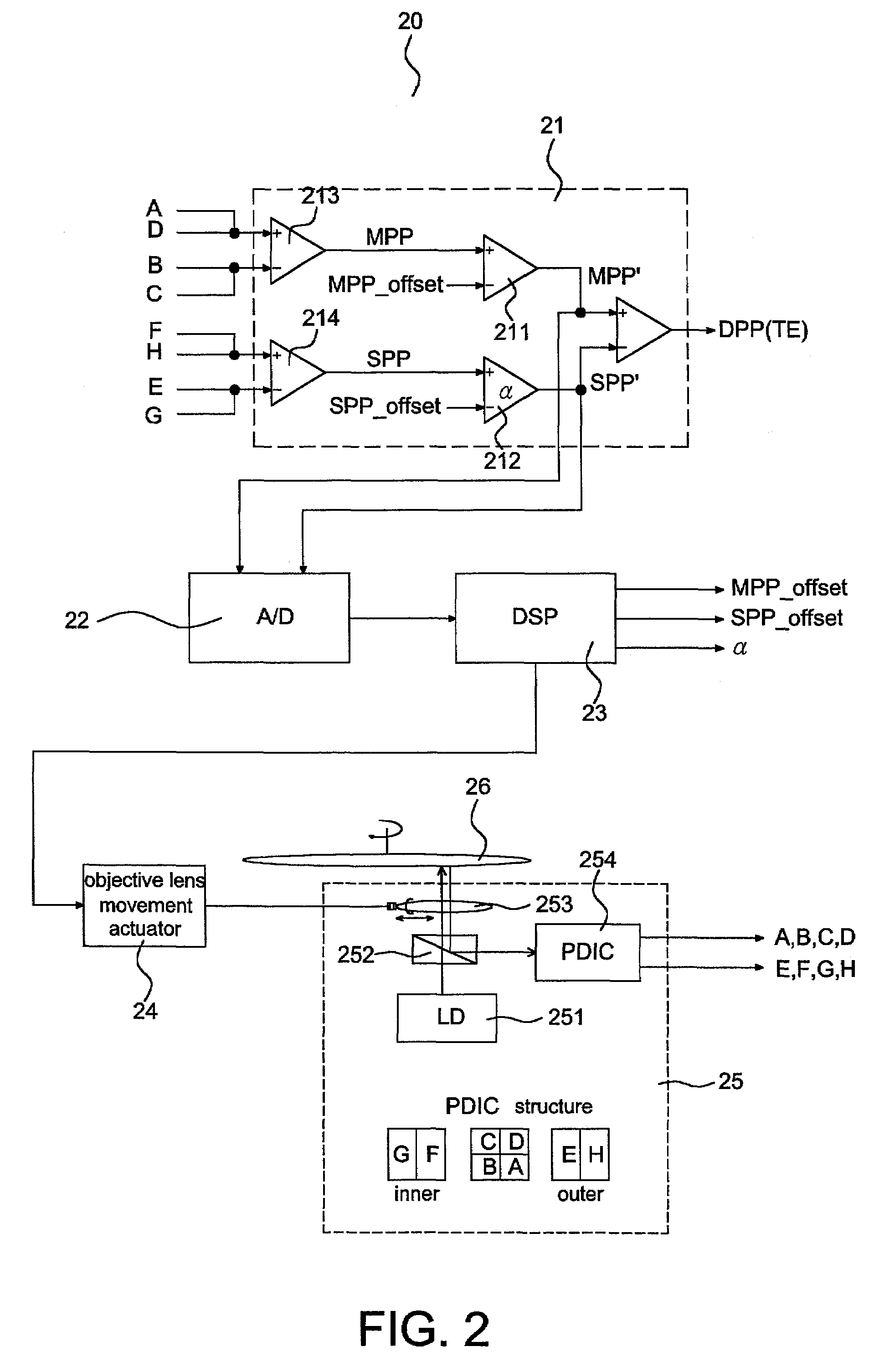
[0037]FIG. 2 shows a calibration system for DPP tracking error signals of the invention. The calibration system 20 includes a front-stage amplifier or a radio frequency IC (RFIC) 21, an analog / digital converter (A / D) 22, a digital signal processor (DSP) 23, an objective lens movement actuator 24, and an optical device 25.

[0038]The front-stage amplifier 21 receives the signals (A, B, C, D, E, F, C H) of the pick-up head outputted from the optical signal detector and amplifier 254, amplifies the signals, and synthesizes the signals to be signals needed for the track-locking servo control. The signals include a push-pull signal MPP′ of the main beam...


PUM

PropertyMeasurementUnit
angleaaaaaaaaaa
fixed angleaaaaaaaaaa
frequencyaaaaaaaaaa

Abstract

A gain calibration device and method for differential push-pull (DPP) tracking error signals in an optical storage system is provided. The gain calibration method processes the synthesized gain (SPPG) of the sub beam in the DPP tracking error signal components with respect to the main beam. The calibration theorem resides in controlling the objective lens of the pick-up head to form a lens-shift or controlling the tilt of the objective lens relative to the optical disc to make the synthesized DPP tracking error signals generate a correspondingly signal variation owing to the optical path deviation. The synthesized gain is calibrated to make the signal variation a minimum value, and the calibrated synthesized gain is the optimum value. In the method and device of the invention, the optimum synthesized gain of the sub beam is precisely computed without the assumptions of equal intensity of the two sub beams and symmetrical positions of the two sub beams with respect to the main beam, and without knowing the ratio of the pitch between the two sub beams to the track pitch.

Description

BACKGROUND OF THE INVENTION[0001]1. Field of the Invention[0002]The invention relates to a gain calibration device and method for differential push-pull (hereinafter referred to as DPP) tracking error signals in an optical storage system, and more specifically to a calibration device and method for calibrating the sub beam in the DPP signal component with respect to the synthesized gain (hereinafter referred to as SPPG) of the main beam.[0003]2. Description of the Related Art[0004]FIG. 1 shows the configuration of laser spots on optical discs for the DPP-based tracking error synthesis. As shown in FIG. 1, in the general DPP-based tracking error synthesis, there are three laser beams, including a main beam 12, a first sub beam 13, and a second sub beam 14, projected on the optical disc. Therefore, the DPP tracking error signal TE may be represented as the differential synthesis of the push-pull signal MPP of the main beam 12 and the push-pull signals SPP of the sub beams 13 and 14, a...

Claims


Application Information

Patent Timeline
Patent Type & Authority Patents(United States)
IPC IPC(8): G11B7/095G11B7/09G11B27/10
CPCG11B7/0945G11B7/0903G11B7/094G11B7/0956G11B7/0941
Inventor WU, WEN-YIHSU, JIN-CHUANHSU, BRUCE
Owner MEDIATEK INC
Why Eureka
Try Eureka