Vapor compression systems using an accumulator to prevent over-pressurization

a technology of accumulator and vapor compression system, which is applied in the direction of gas cycle refrigeration machine, refrigeration machine, lighting and heating apparatus, etc., can solve the problems of accumulator not being sized to determine the maximum pressure, damage to the components, and inability to prevent over-pressurization of the system, so as to prevent over-pressurization

Inactive Publication Date: 2006-04-11
CARRIER CORP
View PDF11 Cites 14 Cited by
  • Summary
  • Abstract
  • Description
  • Claims
  • Application Information

AI Technical Summary

Benefits of technology

[0010]The bulk density in the system is the system volume divided by the mass of the refrigerant in the system. Therefore, by dividing the mass of the refrigerant by the maximum desired storage density, an overall desired system volume can be determined. The total volume of the system without the accumulator can be subtracted from the overall desired system volume to calculate the optimal accumulator volume. The optimal accumulator volume is used to size the accumulator such that the accumulator can prevent over-pressurization of systems when stored at a storage temperature near or above the critical temperature of the refrigerant in the system.

Problems solved by technology

Chlorine containing refrigerants have been phased out in most of the world due to their ozone destroying potential.
The system components (compressor, condenser / gas cooler, expansion device, evaporator and refrigerant lines) are designed to withstand a maximum pressure, but exposure to higher pressures may result in damage to the components.
For carbon dioxide (CO2) systems, however, this becomes an issue because the critical point is very low (88° F.).
However, the accumulator is not sized to determine a maximum pressure when the system is inactive or in storage.

Method used


Image

  • Vapor compression systems using an accumulator to prevent over-pressurization
  • Vapor compression systems using an accumulator to prevent over-pressurization
  • Vapor compression systems using an accumulator to prevent over-pressurization

Examples


Embodiment Construction

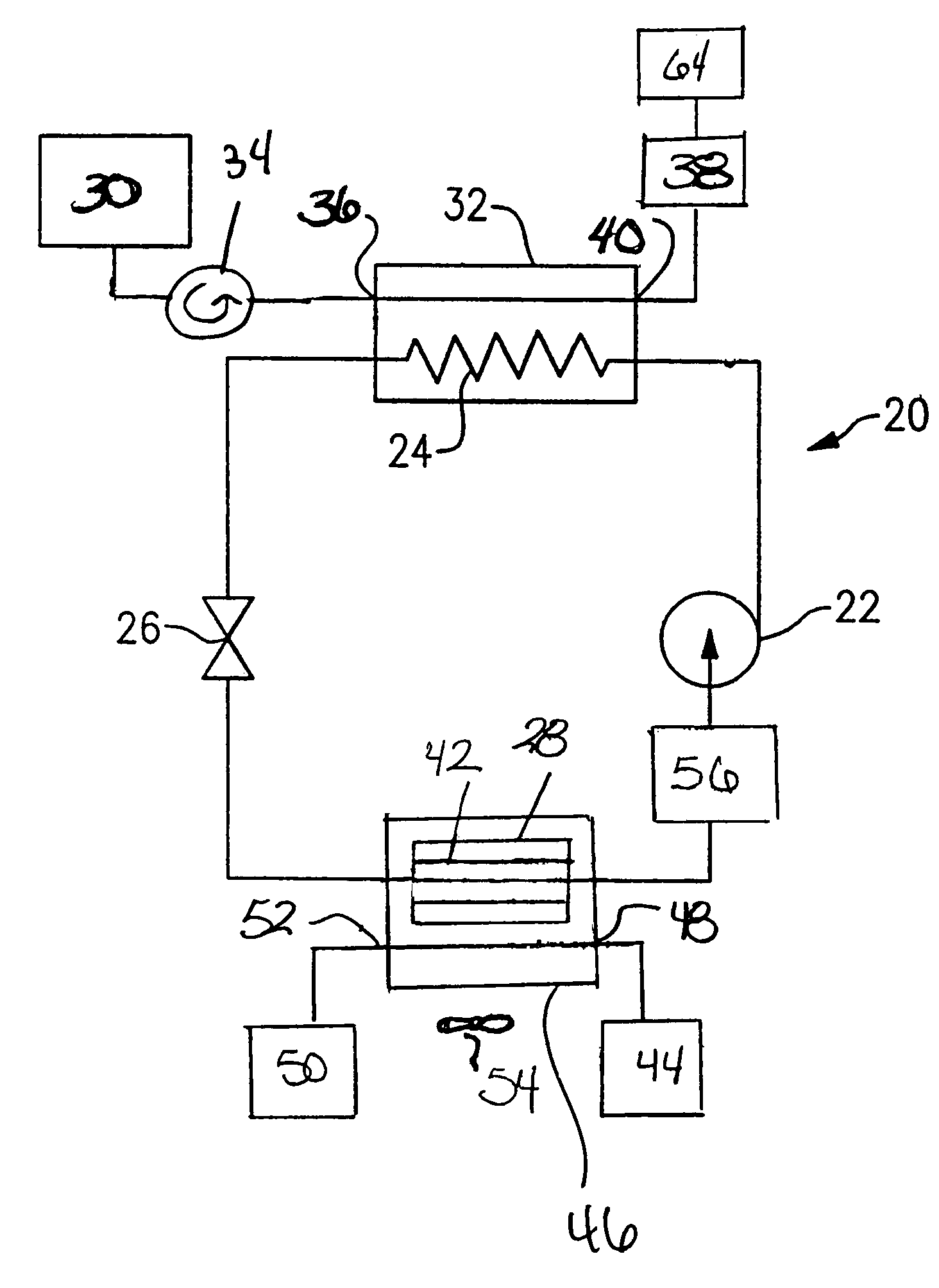
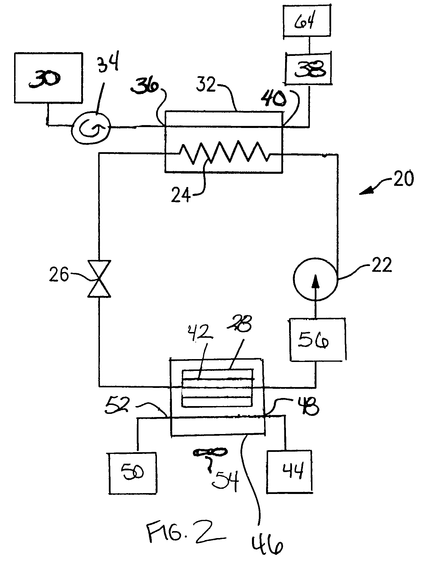
[0015]FIG. 2 illustrates an example vapor compression system 20 including a compressor 22, a heat rejecting heat exchanger (a gas cooler in transcritical cycles) 24, an expansion device 26, and a heat accepting heat exchanger (an evaporator) 28. Refrigerant circulates through the closed circuit system 20 through refrigerant lines.

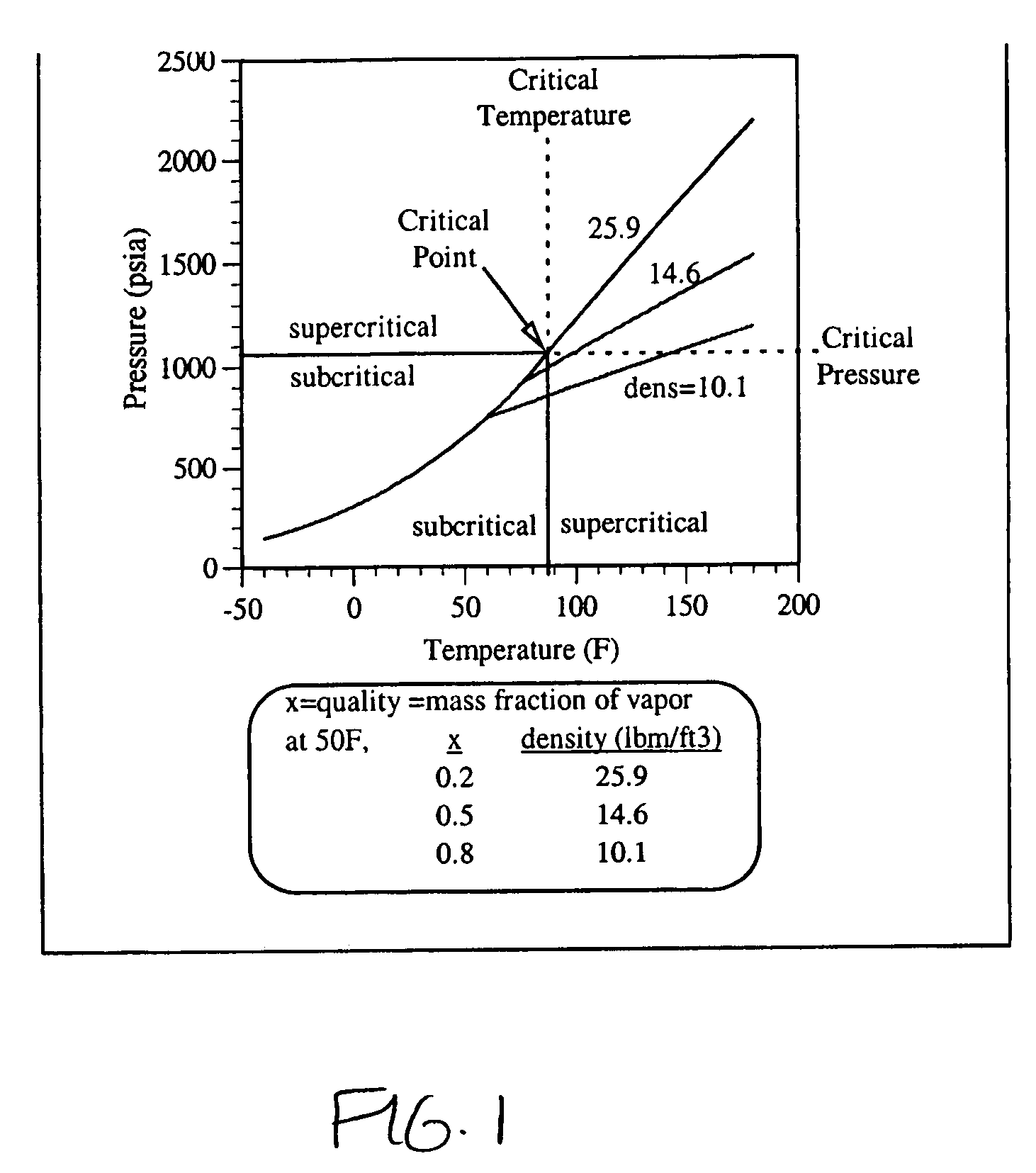
[0016]In one example, carbon dioxide is used as the refrigerant. Because carbon dioxide has a low critical point, systems utilizing carbon dioxide as a refrigerant usually run transcritically. Although carbon dioxide is described, other refrigerants may be used.

[0017]The refrigerant exits the compressor 22 at a high pressure and a high enthalpy. The refrigerant then flows through the heat rejecting heat exchanger 24 at a high pressure. A fluid medium 30, such as water or air, flows through a heat sink 32 of the heat rejecting heat exchanger 24 and exchanges heat with the refrigerant flowing through the heat rejecting heat exchanger 24. In the heat rejecting...


PUM

PropertyMeasurementUnit
storage pressureaaaaaaaaaa
critical pointaaaaaaaaaa

Abstract

An accumulator acts as a buffer to prevent over-pressurization of the vapor compression system while inactive. By determining the maximum storage temperature and the maximum storage pressure a system will be subject to when inactive, a density of the refrigerant for the overall system can be calculated. Dividing the density by the mass of the refrigerant determines an optimal overall system volume. The volume of the components is subtracted from the overall system volume to calculate the optimal accumulator volume. The optimal accumulator volume is used to size the accumulator so that the accumulator has enough volume to prevent over-pressurization of the system when inactive.

Description

BACKGROUND OF THE INVENTION[0001]The present invention relates generally to a vapor compression system including an accumulator sized to protect the system against over-pressurization when inactive.[0002]Chlorine containing refrigerants have been phased out in most of the world due to their ozone destroying potential. “Natural” refrigerants, such as carbon dioxide and propane, have been proposed as replacement fluids. Carbon dioxide has a low critical point, which causes most air conditioning systems utilizing carbon dioxide as a refrigerant to run transcritically, or partially above the critical point, under most conditions, including when inactive. Under transcritical operations, pressure within the system becomes a function of both temperature and density.[0003]A vapor compression system usually operates under a wide range of operating conditions. External atmosphere conditions, including temperature, can affect the pressure of the system while inactive. The system components (co...

Claims


Application Information

Patent Timeline
Patent Type & Authority Patents(United States)
IPC IPC(8): F25B43/00F25B9/00F25B45/00
CPCF25B9/008F25B43/006Y10T29/49394F25B2309/061F25B2500/01F25B45/00
Inventor SIENEL, TOBIAS H.CHEN, YU
Owner CARRIER CORP
Why Eureka
Try Eureka