Injector to inject fuel into a combustion chamber

a technology of injector and combustion chamber, which is applied in the direction of corrosion prevention fuel injection, machine/engine, operating means/releasing devices of valves, etc., can solve the problems of actuator housing, seal damage, actuator housing cannot be replaced,

Inactive Publication Date: 2006-04-11
VITESCO TECH GERMANY GMBH
View PDF16 Cites 13 Cited by
  • Summary
  • Abstract
  • Description
  • Claims
  • Application Information

AI Technical Summary

Benefits of technology

[0008]The object of the invention is to specify an injector to inject fuel into a combustion chamber in which it is possible to incorporate a corrosion protection layer in the indentation of the injector housing and at the same time prevent leakage along the interfaces between the injector housing and the actuator housing.
[0009]The problem is resolved by an injector to inject fuel into a combustion chamber with the following features. The injector features an actuator housing and an injector housing. The injector housing features an indentation in which part of the actuator housing is located. A bottom surface of the indentation of the injector housing is formed by a surrounding support surface for the actuator housing. A seal is located between the injector housing and the actuator housing to prevent leakage along interfaces between the injector housing and the actuator housing. An underside of the actuator housing that is adjacent to the support surface of the injector housing features a peripheral recess. The recess of the underside of the actuator housing is such that the underside of the actuator housing has at least one peripheral projection which is oriented towards the support surface of the injector housing and is adjacent to the support surface of the injector housing. The seal is located in the recess on the underside of the actuator housing and stretched around the projection of the underside of the actuator housing. The seal is adjacent to the support surface of the injector housing.
[0010]Since the seal is located on the underside of the actuator housing and not on side surfaces of the actuator housing, there is no contact between the seal and the side surfaces of the indentation, so that the actuator housing can be introduced into the indentation without friction between the seal and the indentation. In consequence the indentation can be coated with a corrosion protection layer, whereas because of the presence of the seal leakage along the interfaces between the injector housing and the actuator housing is prevented.
[0011]The seal can also be fitted into the recess significantly more easily than before since the seal does not have to be stretched over a projection extending sideways which requires increased extension of the seal.
[0017]With this type of injector the seal can be fitted more easily into the recess. A further advantage is that the indentation of the injector housing can be manufactured with less effort, as will be explained below. For the creation of the indentation the groove edge of the injector housing is initially chamfered between the side walls of the indentation and the support surface of the injector housing. An actuator housing with non-chamfered edges cannot be introduced into such an indentation up to the support surface of the injector housing. Further work must be done on the indentation beforehand by widening the groove edges so that the edges of the actuator housing fit into the widened groove edges. It is possible to dispense with this additional measure if the recess on the underside of the actuator housing is such that the underside features only one peripheral projection. In this case the outer problem edge of the actuator housing is not actually present at all. What is involved here is a sharp chamfering of the edge. The indentation of the injector housing can consequently be manufactured with less effort. Over and above this a widening of the groove edge of the injector housing is also disadvantageous for the resistance of the injector to high pressure since increased notch stresses occur.
[0020]So that the seal does not slip out of the recess in the underside of the actuator housing before the actuator housing is inserted into the injector housing, it is advantageous for the projection to be designed in such a way that its surface adjacent to the side surface of the indentation of the injector housing is at an angle. The angle here is such that the projection in the area of the support surface of the injector housing is closer to the side surfaces of the indentation than in the area of its shoulder.

Problems solved by technology

This represents a particular disadvantage if the indentation is to be coated with a corrosion protection layer.
It has become evident that the friction between the seal and the corrosion protection layer is so great that either the actuator housing cannot be inserted into the injector housing or the seal is destroyed when the actuator housing is pushed into the injector housing.

Method used


Image

  • Injector to inject fuel into a combustion chamber
  • Injector to inject fuel into a combustion chamber
  • Injector to inject fuel into a combustion chamber

Examples


Embodiment Construction

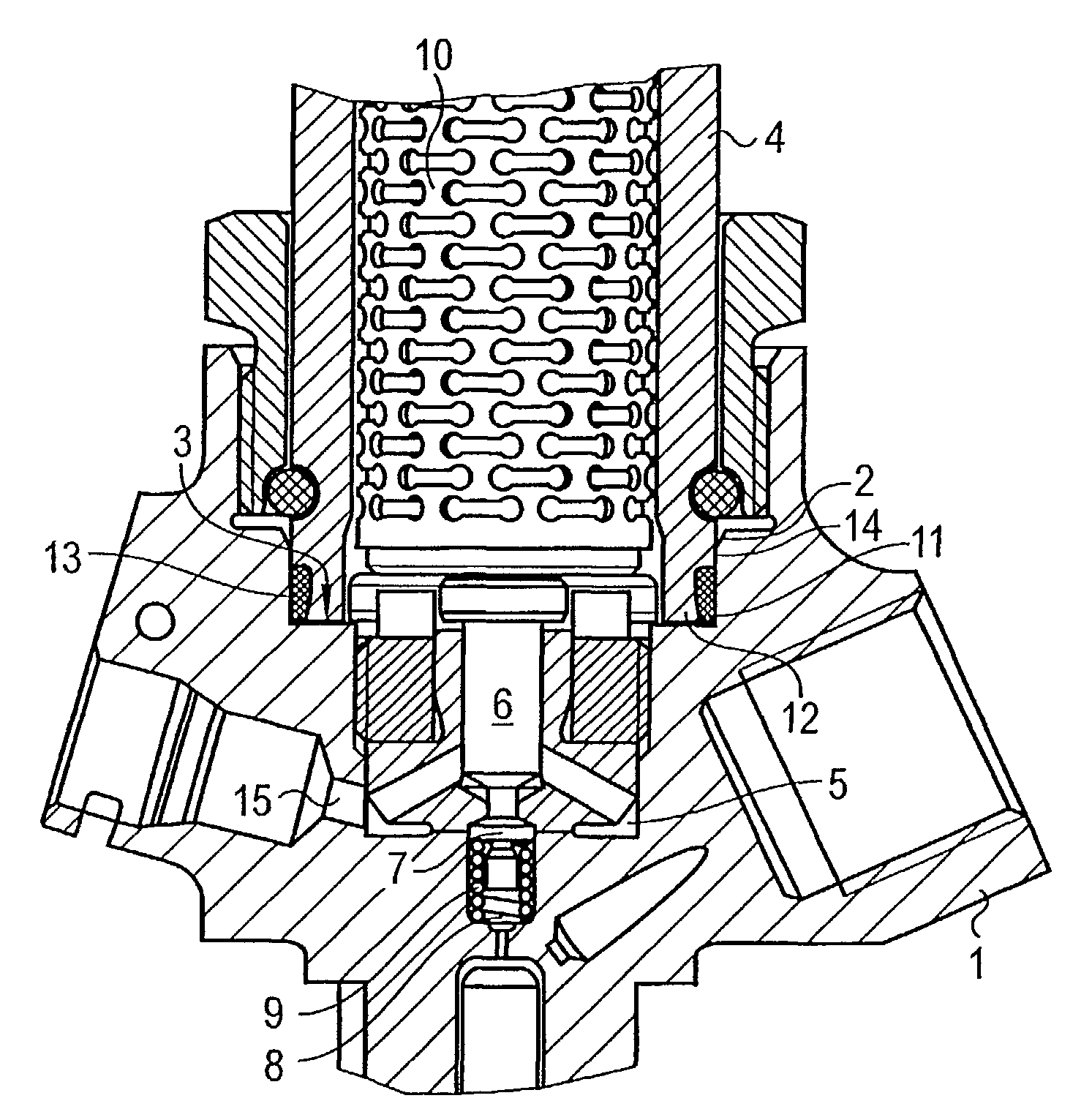
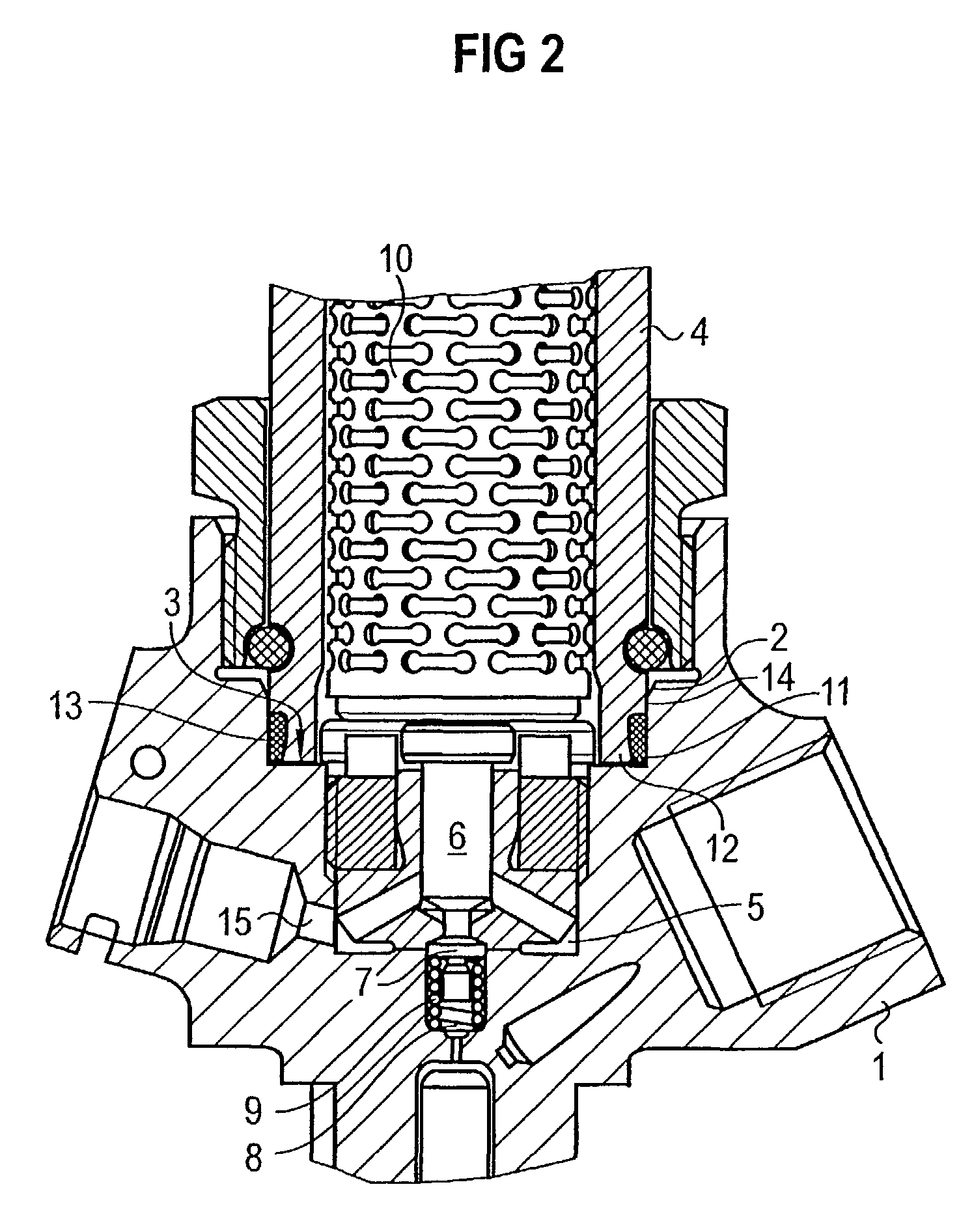
[0023]FIG. 2 shows a cross section through a part of an injector with an actuator, an actuator housing, a seal, a projection, a recess, an indentation, a support surface, a further indentation, a valve piston, a valve head, a control chamber and an injector housing.

[0024]The injector features an injector housing 1 with an indentation 2. The indentation 2 of the injector housing 1 is coated with an appr. 2–3 μm thick corrosion protection layer 14. Corrosion protection layer 14 consists of zinc phosphate.

[0025]A bottom surface of indentation 2 of injector housing 1 is formed by a peripheral support surface 3 for an actuator housing 4. In the middle of indentation 2 injector housing 1 features a further indentation 5. In the further indentation 5 a valve piston 6 and a valve head 7 are located which are in contact with each other. Valve head 7 separates a control chamber 8 from a return line 15. Valve head 7 is pressed into its valve seat by a spring 9 located in control chamber 8. A p...


PUM


Abstract

An injector housing (1) of the injector has an indentation (2) in which a part of an actuator housing (4) of the injector is located. A floor of said indentation (2) is formed by a peripheral support surface (3) for the actuator housing (4). A bottom surface of the actuator housing (4) is oriented towards the support surface (3) and has a peripheral recess (11). This recess (11) is such that the bottom surface of the actuator housing (4) has at least one peripheral projection (12), which is oriented towards the support surface (3) and is adjacent to the support surface (3). A seal (13) for preventing leakage along interfaces between the injector housing (1) and the actuator housing (4) is locate din the recess (11) and is adjacent to the support surface (3).

Description

CROSS REFERENCE TO RELATED APPLICATION[0001]This application is a continuation of copending International Application No. PCT / DE01 / 04168 filed Nov. 6, 2001, which designates the United States, and claims priority to German application number 10055639.6 filed Nov. 10, 2000.TECHNICAL FIELD OF THE INVENTION[0002]The invention relates to an injector for injecting fuel into a combustion chamber.BACKGROUND OF THE INVENTION[0003]An injector of this type generally features an actuator that controls an injection valve. If the injection valve is opened by the actuator fuel is injected into a combustion chamber. For example the actuator operates a servo valve which in its turn hydraulically opens and closes the injection valve. The actuator can be activated electrically. For example the actuator consists of piezo-electric elements and expands when an electrical voltage is applied.[0004]The structure of a typical injector is described on the basis of FIG. 1 that shows a cross section of a part ...

Claims


Application Information

Patent Timeline
Patent Type & Authority Patents(United States)
IPC IPC(8): F02M59/00B05B1/08B05B3/04F02M61/00F02M63/00F02M47/02F02M59/46F02M61/16
CPCF02M47/027F02M61/16F02M63/0026F02M61/166F02M2200/16F02M2200/05
Inventor MOHR, MARKUS
Owner VITESCO TECH GERMANY GMBH
Why Eureka
Try Eureka