Apparatus and method for controlling a reciprocating compressor

a reciprocating compressor and apparatus technology, applied in the direction of dynamo-electric converter control, motor/generator/converter stopper, pump parameter, etc., can solve the problems of cost increase, error of calculation, inability to precisely control the compressor, etc., to achieve the effect of precisely controlling the piston stroke of the compressor and inexpensive control of the compressor

Inactive Publication Date: 2006-04-11
LG ELECTRONICS INC
View PDF13 Cites 27 Cited by
  • Summary
  • Abstract
  • Description
  • Claims
  • Application Information

AI Technical Summary

Benefits of technology

[0037]Therefore, an object of the present invention is to solve the problems involved in the prior art and to provide an apparatus and method for controlling a reciprocating compressor capable of inexpensively and exactly controlling a piston stroke of a compressor.
[0041]The research can provide an apparatus for controlling the reciprocating compressor capable of inexpensively and exactly controlling the piston stroke. Specifically, the phase difference between a phase of the current supplied to a motor of the compressor and a phase of the stroke is set to a fluctuation point, and an input voltage when having the set phase difference is determined as a target output voltage.

Problems solved by technology

Firstly, because the critical value of the dead point of the displacement of the piston has to be exactly calculated, the complicated calculation of the dead point of the displacement causes to an error. Specifically, it is necessary to carry out the complicated calculation such as equations 1 and 2, thereby producing an error of the calculation.
Secondly, since expensive apparatuses such as a computer are used to carry out the complicated calculation, the cost increases.
Therefore, it is impossible to exactly control the compressor.
However, the prior apparatus and method for controlling the reciprocating compressor disclosed in the Japanese Patent Laid-Open Publication has following disadvantage.
In order to control the frequency of the power supplied to the compressor, an expensive apparatus (inverter) has to be provided.
Accordingly, since the cost of components is increased, it is impossible to provide an inexpensive control apparatus.

Method used


Image

  • Apparatus and method for controlling a reciprocating compressor
  • Apparatus and method for controlling a reciprocating compressor
  • Apparatus and method for controlling a reciprocating compressor

Examples


Embodiment Construction

[0081]Now, preferred embodiments of the present invention will be described in detail with reference to the annexed drawings.

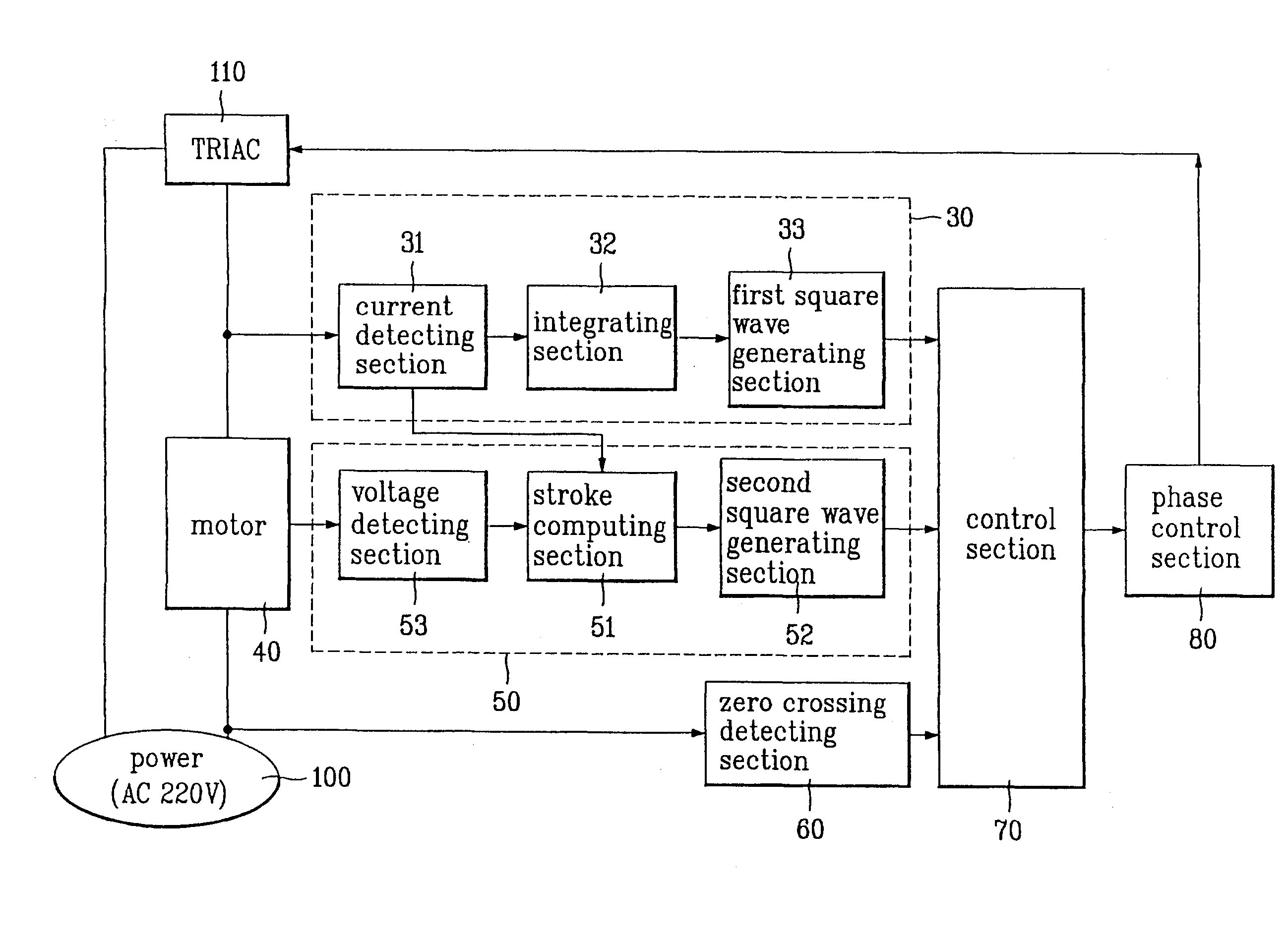
[0082]FIG. 5 is a block diagram of an apparatus for controlling a reciprocating compressor according to a first preferred embodiment of the present invention, and FIG. 6 is a detail diagram of a control section of FIG. 5.

[0083]The control apparatus of the reciprocating compressor according to the first embodiment of the present invention comprises, as shown in FIG. 5, a power supply section 100 for supplying a common power (alternate current of 100 to 220 V), a TRIAC 110 for switching the common power supplied from the power supply section 100 in response to a triggering signal, a current phase detecting section 30 for detecting a current supplied to the compressor through the TRIAC 110 to produce a first square wave corresponding to the detected current, a motor 40 for reciprocating a piston in a cylinder of the compressor according to the switched common pow...


PUM


Abstract

Disclosed is an apparatus and method for controlling a reciprocating compressor capable of inexpensively and exactly controlling a position of a piston in a cylinder, by which a top clearance is minimized according to the information of a phase difference between a square wave of a piston stroke and a square wave of a current supplied to the compressor. The apparatus comprises a driving section for driving the reciprocating compressor by varying an angle or ignition in response to a control signal; a current phase detecting section for outputting a square wave corresponding to the detected current supplied to the compressor; a stroke phase detecting section for outputting a square wave corresponding to a stroke of the compressor; and a control section for controlling the angle of ignition of the driving section according to the phase difference between the square wave produced from the current phase detecting section and the square wave produced from the stroke phase detecting section.

Description

TECHNICAL FIELD[0001]The present invention relates to a reciprocating compressor, and more particularly to an apparatus and method for controlling a reciprocating compressor by controlling an output voltage according to a phase difference between a piston stroke waveform and a current waveform of the reciprocating compressor.BACKGROUND ART[0002]Recently, a reciprocating compressor has been developed to compress a refrigerant gas in a refrigerator and so on.[0003]U.S. Pat. No. 5,342,176 discloses a reciprocating compressor using a linear motion motor and a method for controlling a piston stroke of the reciprocating compressor.[0004]FIG. 1 is a cross sectional view illustrating the construction of a reciprocating compressor disclosed in U.S. Pat. No. 5,342,176, and FIG. 2 is a block diagram illustrating a compressor controlling apparatus for controlling a piston stroke of the refrigerant shown in FIG. 1.[0005]According to the conventional reciprocating compressor, as shown in FIG. 1, ...

Claims


Application Information

Patent Timeline
Patent Type & Authority Patents(United States)
IPC IPC(8): F04B49/06
CPCF04B49/065F04B2201/0201F04B2203/0402F04B2203/0401F04B2201/0206
Inventor JEUN, YOUNG-HWAN
Owner LG ELECTRONICS INC
Why Eureka
Try Eureka