
Carburetor air flow structure

a technology of air flow structure and carburetor, which is applied in the direction of machines/engines, combustion air/fuel air treatment, combustion-air/fuel-air treatment, etc., can solve the problems of reducing the overall volume and mass of fuel and air available to the engine, affecting the quality of combustion within the engine, and reducing the production of power by the engine. achieve the effect of engine performan

Inactive Publication Date: 2006-04-11
PETERSON LONN M
View PDF18 Cites 25 Cited by
  • Summary
  • Abstract
  • Description
  • Claims
  • Application Information

AI Technical Summary

Benefits of technology

[0008]The present invention includes a variable geometry air box which includes one or more air flow control valves within the air box. The valves may be opened to intermediate settings between fully opened and fully closed, thereby permitting the user to tune the air box in order to obtain desired engine performance.

Problems solved by technology

Depending on the geometry of the various carburetor components such as the throttle, jets and throat, the venturi effect can either promote or retard fuel / air mixing and fuel atomization, which ultimately affects the quality of combustion within the engine.
In general, efforts to atomize the fuel more thoroughly tend to diminish air velocity, thereby diminishing the production of power by the engine since, while well mixed, the overall volume and mass of fuel and air available to the engine has been reduced.
Since the airbox is designed as an air filter its airflow characteristics are necessarily somewhat restrictive, arguably resulting in reduced engine performance.
Other researches feel that a completely “open” (nothing between the atmosphere and the carburetor throat) improves performance, although admittedly at the cost of engine life due to the introduction of contaminants.
Unfortunately, for a given internal combustion engine operating in a given environment, there will be some optimum air box airflow characteristic which cannot be satisfied by a fixed air box geometry, due to the phenomenon of air box resonance.
However, the variations in engine characteristics, the individual characteristics of the vehicle to which the engine is attached, altitude above sea level, relative humidity, air filter cleanliness and the speed range at which a vehicle user may wish to operate most frequently are not identical, thereby causing a fixed geometry air box to offer compromised performance in most real world applications.

Method used


Image

  • Carburetor air flow structure
  • Carburetor air flow structure
  • Carburetor air flow structure

Examples


Embodiment Construction

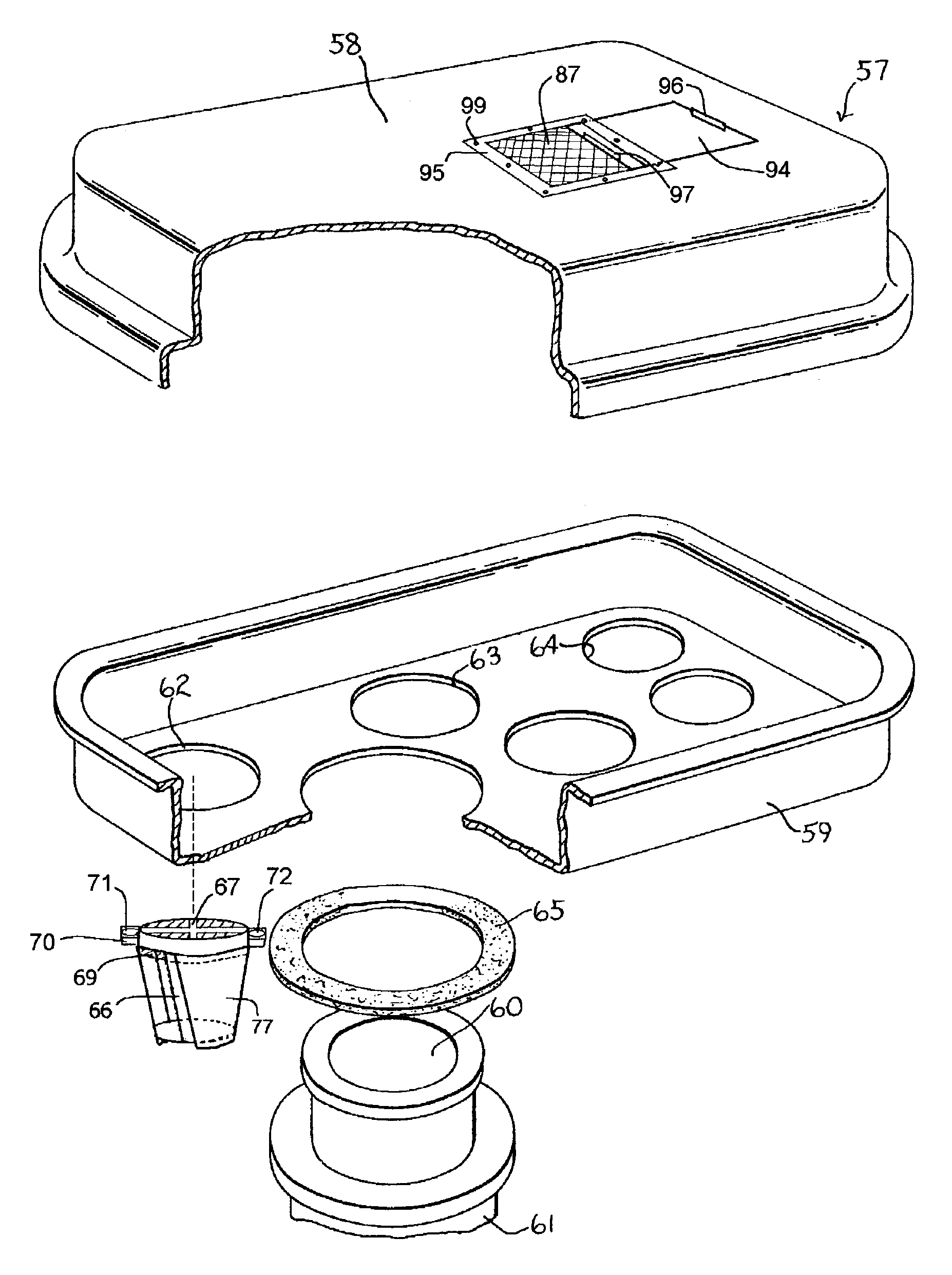
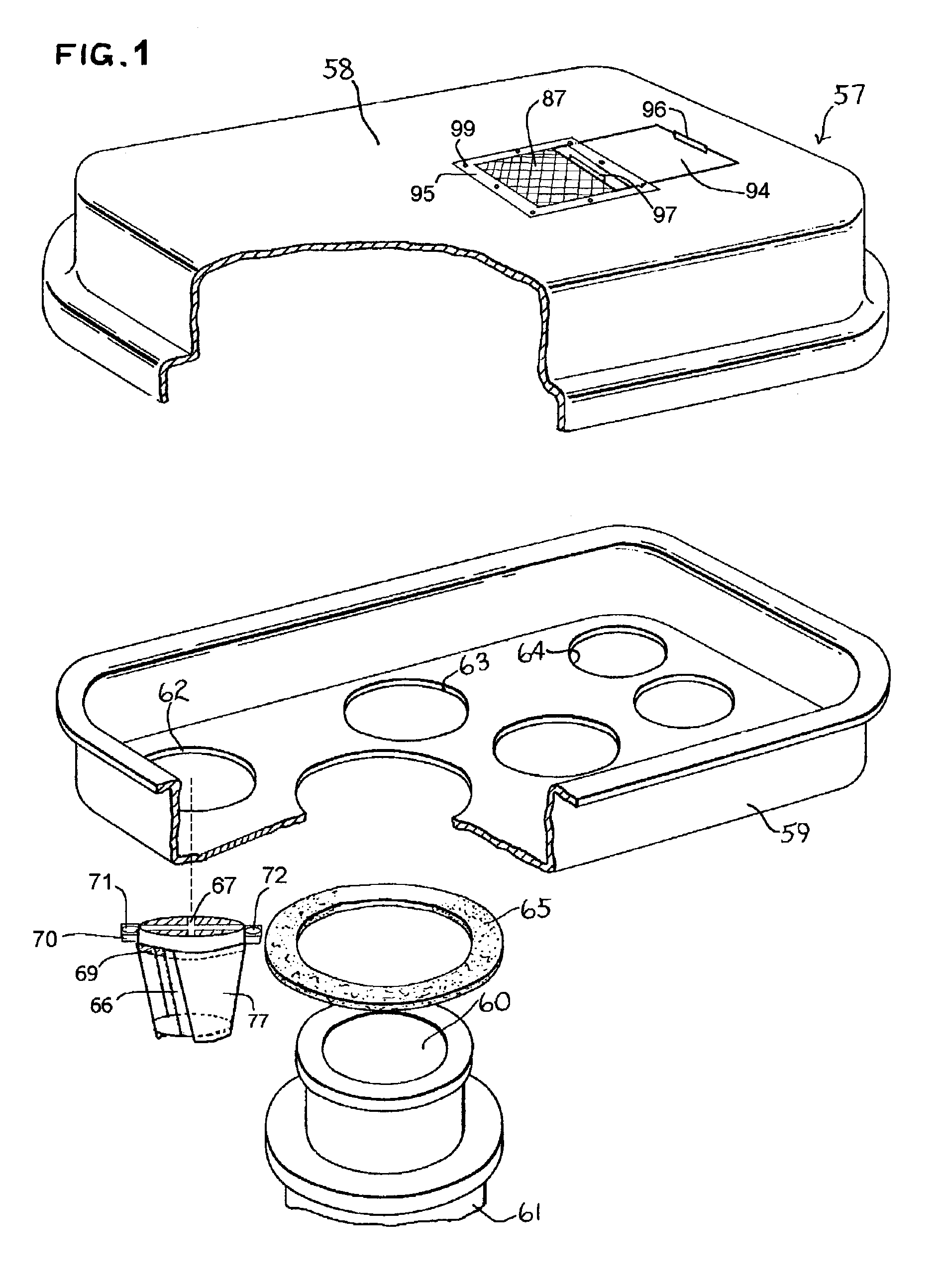
[0025]Referring to FIG. 1, an air box 57 is depicted that serves to filter and regulate the quantity of air reaching the carburetor air inlet of an internal combustion engine. The numeral 60 designates the inlet end portion of the combustion air duct which introduces air to a carburetor via air hose 61. The air box 57 is formed to include a top half 58 and a bottom half 59. Air enters the air box 57 through a plurality of orifices such as orifices 62, 63 and 64.

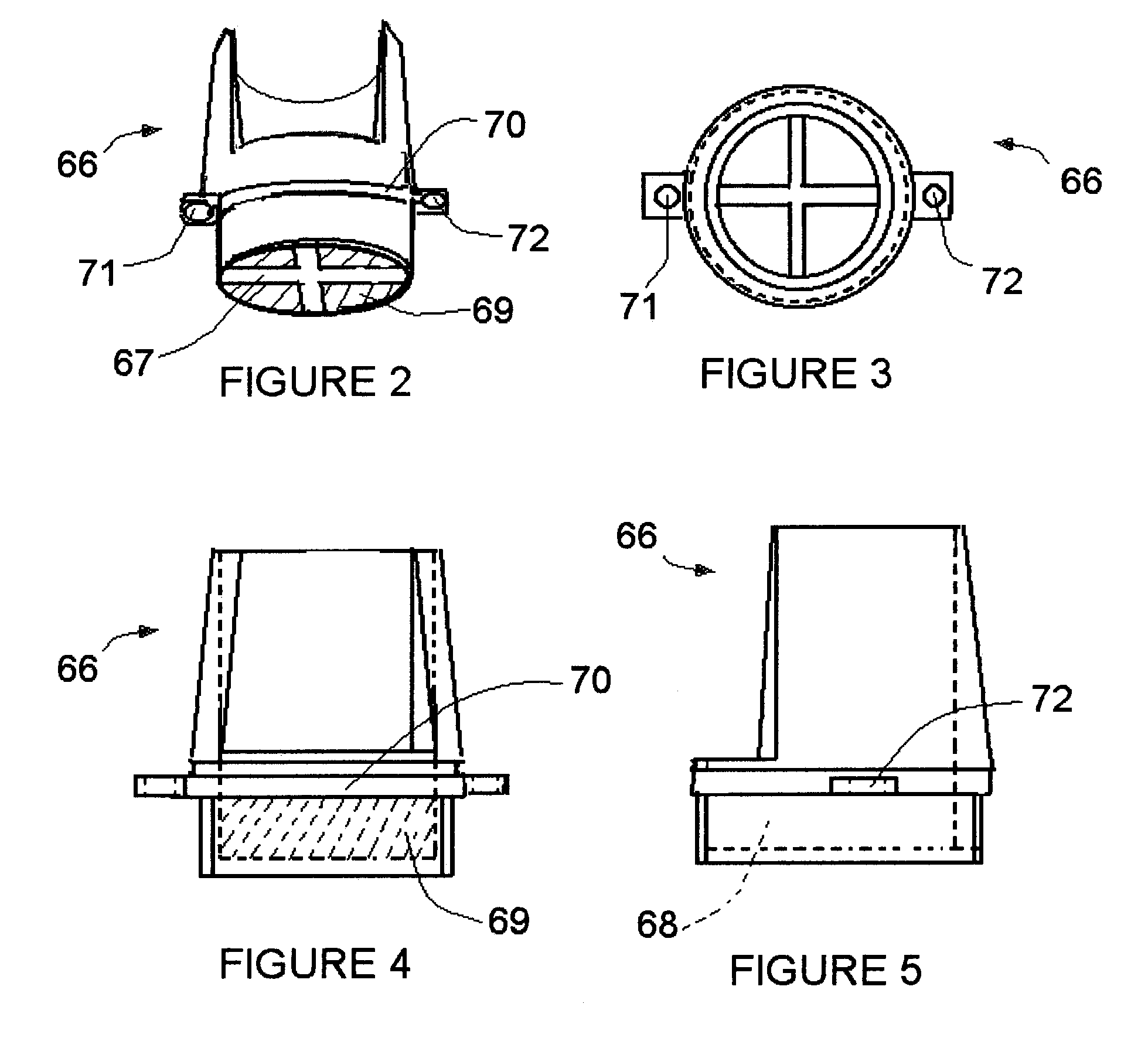
[0026]Referring also to FIGS. 2, 3, 4 and 5, an air intake valve body 66 is depicted. Inserted into the interior 68 of the body 66 is a circular filter element 69. The filter element is constructed of any suitable air permeable material such as foam polyurethane or similar resilient material. The element 69 is retained within the body 66 by trap or screen 67. A flange 70 surrounds the body 66 and provides a platform by which the body 66 is mounted to the air box 57. The bottom 76 of body 66 is inserted into one of the orifice...


PUM


Abstract

Air flow from the airbox (57) to the carburetor of an internal combustion engine is regulated by a plurality of valve bodies (66) fitted with rotatable lids (77) which permit infinite adjustment of air flow between a fully closed and fully open position. In an alternate embodiment, a rectangular valve is used that has a relatively lower profile and uses a sliding door (94) to permit manual adjustment of airflow to the airbox (57).

Description

FIELD OF THE INVENTION[0001]This invention relates generally to the field of carburetion within an internal combustion engine, and more particularly to regulation of air intake through the throat of a carburetor.DESCRIPTION OF RELATED TECHNOLOGY[0002]A typical internal combustion engine includes a carburetor within which fuel and air are mixed in order to provide the correct fuel / air ratio needed to support combustion in the engine cylinders. The carburetor structure typically includes a throat that is shaped to function as a venturi, which has the effect of increasing velocity of air passing through the carburetor throat. Depending on the geometry of the various carburetor components such as the throttle, jets and throat, the venturi effect can either promote or retard fuel / air mixing and fuel atomization, which ultimately affects the quality of combustion within the engine.[0003]Since one effect of the venturi is to increase the velocity of air flow through the carburetor throat, ...

Claims


Application Information

Patent Timeline
IPC IPC(8): B01D29/90F02D9/16F02M17/34F02M35/02
CPCF02D9/16F02M35/02F02M17/34Y10S55/28
Inventor PETERSON, LONN M.
Owner PETERSON LONN M
Learn More