Methods for forming complex-shaped components in a heated polymeric film
What is Al technical title?
Al technical title is built by PatSnap Al team. It summarizes the technical point description of the patent document.
a polymer film and complex-shaped technology, applied in the field of medical components, can solve the problems of complex-shaped end caps that are costly and laborious, and the saab method does not allow for making complex-shaped components with close tolerances
Inactive Publication Date: 2006-04-11
COGENTIX MEDICAL
View PDF35 Cites 19 Cited by
Summary
Abstract
Description
Claims
Application Information
AI Technical Summary
This helps you quickly interpret patents by identifying the three key elements:
Problems solved by technology
Method used
Benefits of technology
[0010]The present invention provides a method capable of forming complex-shaped medical components in a heated polymeric film to provide thin-walled, durable, low-cost components that may be manufactured to close tolerances, which has been problematic in the prior art. In an exemplary embodiment of the present invention, the method of forming a thin-walled polymeric component includes the steps of heating a portion of the polymeric film to a malleable temperature, and using a forming tool to form a protrusion in the film's heated portion while the polymeric film is malleable. The formed protrusion has an open proximal end, a distal end spaced apart from the proximal end, and sidewalls extending between the proximal and distal ends. The sidewalls and distal end define a first shape of the protrusion and also define an interior of the protrusion. The forming tool has a shaping portion that may have a selected complex shape that is different than the protrusion's first shape. The method further includes the step of exerting a force radially inwardly on the protrusion and moving the protrusion into firm engagement with the forming tool's shaping portion so the protrusion moves from the first shape to a second shape that closely conforms to the selected shape of the forming tool's shaping portion.
Problems solved by technology
The complex-shaped endcap can be a costly and laborious component to manufacture for the sheath assembly.
The resulting sheath is limited to having a relatively simple geometrical shape.
The method of Saab does not sufficiently allow for making complex-shaped components having close tolerances.
Method used
Image
Click on the blue label to locate the original text in one second.
Reading with bidirectional positioning of images and text.
Examples
Embodiment Construction
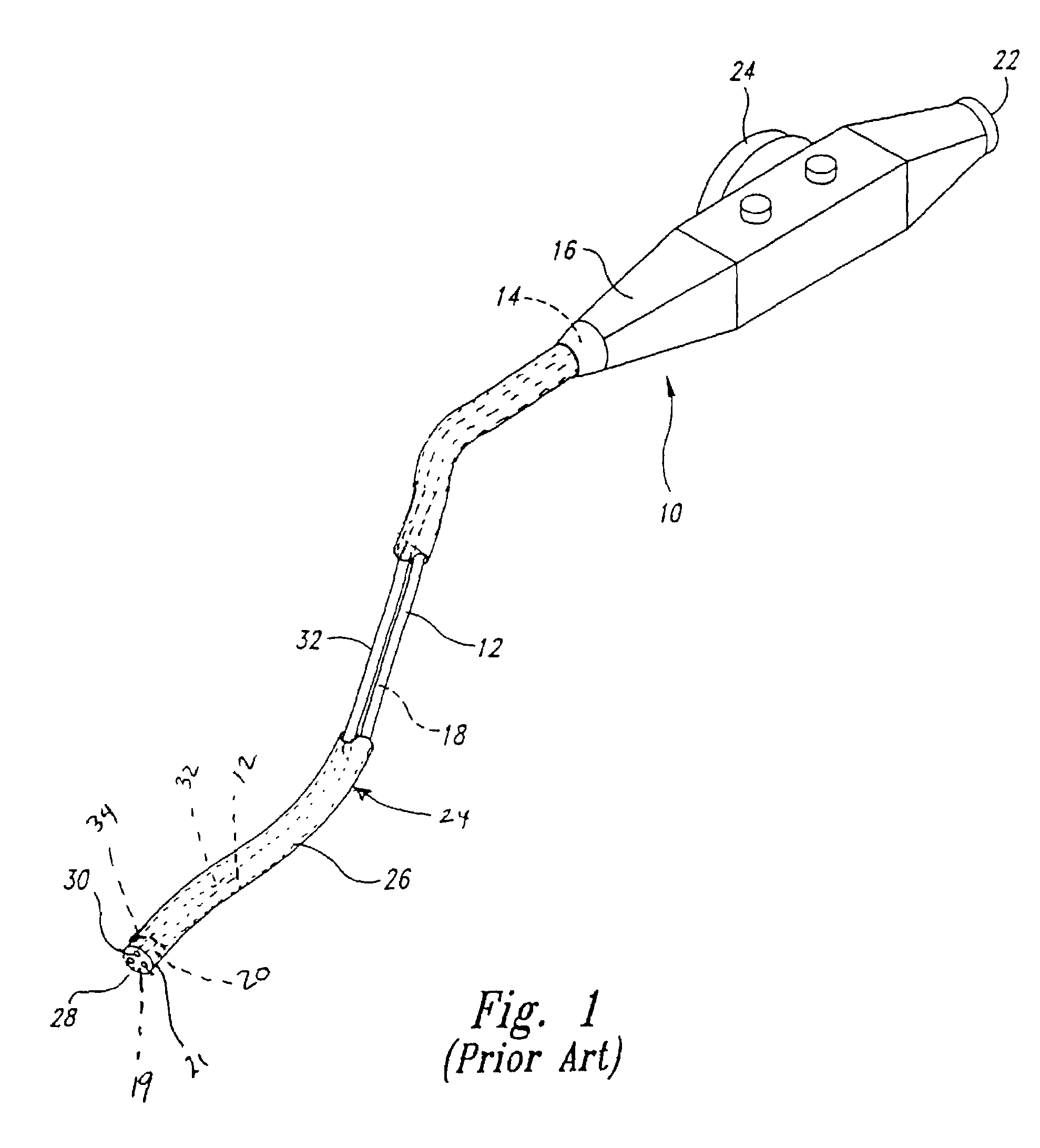
[0022]A thin-walled polymeric medical component 50 having a complex shape made in accordance with one embodiment of the present invention is described herein with reference to the attached drawings. An exemplary embodiment of a thin-walled medical component 50, shown in FIG. 3, is attached to a distal end 52 of a sheath 54. The sheath 54 is shaped and sized to receive and isolate, as an example, an endoscope insertion tube 56 shown in phantom lines. The illustrated medical component 50 is a sheath endcap 51 that is sealably attached to the sheath's distal end 52 so as to provide a viewing window therein that allows clear imaging through the endoscope's imaging system 58, also shown in phantom lines.
[0023]The distal end portion 55 of the illustrated insertion tube 56 has a generally C-shaped cross-section and the endcap 51 is formed with a corresponding complex geometrical shape that closely conforms to the insertion tube's distal end portion. More specifically, the C-shaped cross-se...
PUM
Property
Measurement
Unit
wall thickness
aaaaa
aaaaa
wall thickness
aaaaa
aaaaa
shape
aaaaa
aaaaa
Abstract
A thin-walled polymeric component that may have a selected complex shape, and a method of forming the component. The method includes heating a portion of a polymeric film to a selected malleable temperature, and forming a protrusion in the heated portion while it is malleable. The protrusion defines a protrusion having a first shape. The method also includes positioning a forming tool in the protrusion's interior and drawing a partial vacuum from within the protrusion so as to exert a force on the protrusion and move the protrusion's sidewalls inwardly into engagement with the forming tool. As the partial vacuum is drawn, the protrusion moves to a second shape that may be different than the first shape and that closely conforms to the selected shape of the forming tool. The protrusion is cooled below the malleable temperature and the forming tool is then removed. The distal portion of the protrusion having the selected shape forms the polymeric component, and that distal portion is separated from the remaining portion of the protrusion, thereby providing the thin-walled polymeric component.
Description
[0001]This application is a divisional of U.S. patent application Ser. No. 09 / 366,950, filed Aug. 4, 1999, now U.S. Pat. No. 6,579,582 B1 which is a divisional of U.S. patent application Ser. No. 08 / 948,615, filed Oct. 10, 1997, now abandoned.TECHNICAL FIELD[0002]The present invention is directed toward a method of making medical components, and more particularly toward a method of making contoured, thin-walled, complex-shaped medical components usable with intrabody medical devices.BACKGROUND OF THE INVENTION[0003]The use of intrabody medical equipment, such as endoscopes, catheters, and the like, for diagnostic and therapeutic indications is rapidly expanding. To improve performance, the equipment has been optimized to best accomplish the selected purpose. As an example, endoscopes have been optimized and refined so as to provide upper endoscopes for the examination of the esophagus, stomach, and duodenum, colonoscopes for examining the colon, angioscopes for examining blood vesse...
Claims
Application Information
Patent Timeline
Application Date:The date an application was filed.
Publication Date:The date a patent or application was officially published.
First Publication Date:The earliest publication date of a patent with the same application number.
Issue Date:Publication date of the patent grant document.
PCT Entry Date:The Entry date of PCT National Phase.
Estimated Expiry Date:The statutory expiry date of a patent right according to the Patent Law, and it is the longest term of protection that the patent right can achieve without the termination of the patent right due to other reasons(Term extension factor has been taken into account ).
Invalid Date:Actual expiry date is based on effective date or publication date of legal transaction data of invalid patent.