Microarray dispensing with real-time verification and inspection

a microarray and real-time verification technology, applied in the direction of character and pattern recognition, element comparison, flat carrier supports, etc., can solve the problems of improper positioning of spots on slides, affecting the efficiency of the operation, and affecting the spotting accuracy of the solution, so as to improve the spotting accuracy

Inactive Publication Date: 2006-04-11
AGENA BIOSCI
View PDF41 Cites 83 Cited by
  • Summary
  • Abstract
  • Description
  • Claims
  • Application Information

AI Technical Summary

Benefits of technology

[0009]The present invention provides a microarrayer for spotting solution onto a receiving surface in an automated microarray dispensing device. Elements of the present invention include: at least one dispense head for spotting the receiving surface, at least one light source capable of illuminating the receiving surface, at least one camera operating in conjunction with the at least one light source. The at least one camera is capable of acquiring and transmitting surface image data to a computer. The computer is programmed to receive the surface image data and analyze it. The computer will then generate post analysis data based on the analysis of the surface image data. The post analysis data is available for improving the spotting of the solution onto the receiving surface. In a preferred embodiment, the surface image data includes information relating to receiving surface alignment, information relating to spot quality, and receiving surface identification information. In a preferred embodiment, the analysis of the information relating to receiving surface alignment enables the computer to make automatic adjustments to the relative positions of the at least one dispense head and the receiving surface to increase the accuracy of the spotting. In a preferred embodiment, the analysis of the information relating to spot quality identifies a spot as pass or fail. An operator is then able to rework the spot. In a preferred embodiment, the analysis of the receiving surface identification information enables the computer to track each receiving surface. In a preferred embodiment the receiving surface is a plurality of slides.

Problems solved by technology

However, there are significant problems with the prior art devices that detracts from their efficient operation.
A first problem arises due to the fact that as blank slides are cycled through prior art microarrayers, they can become askew or positioned improperly underneath dispensing tips.
This problem results in spots being positioned improperly on the slides.
A second problem can arise even if the slide is positioned correctly under the dispensing tips.
It is possible for the spot to be deposited in the correct position, but be of poor quality and therefore useless as far as experimentation purposes.
This solution is an unacceptable waste of human effort.
However, it has only limited verification functionality with its integrated camera.
This means that it verifies whether or not a spot has been dispensed, without any quality inspection to analyze whether that spot was good or bad.

Method used


Image

  • Microarray dispensing with real-time verification and inspection
  • Microarray dispensing with real-time verification and inspection
  • Microarray dispensing with real-time verification and inspection

Examples


third preferred embodiment

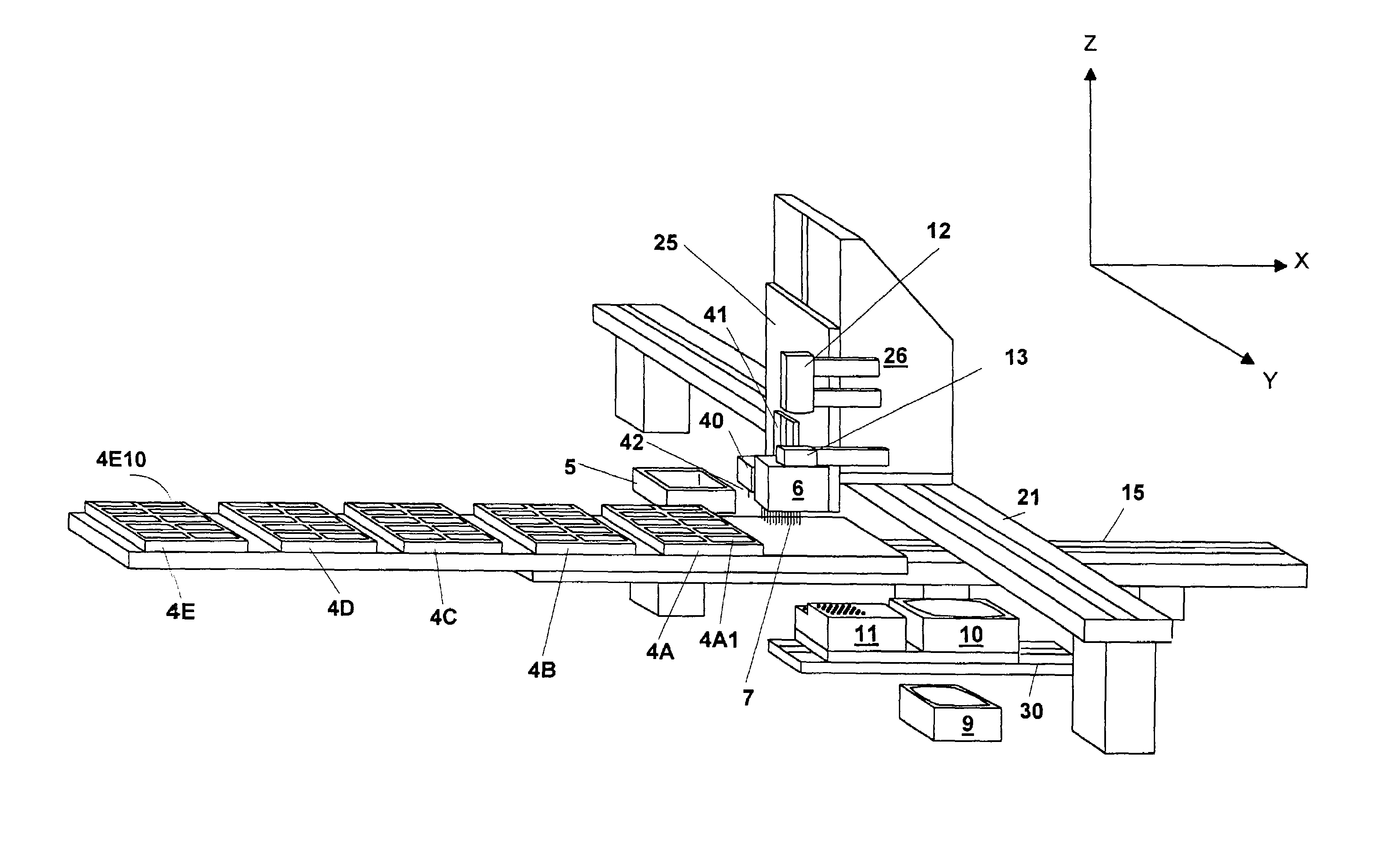
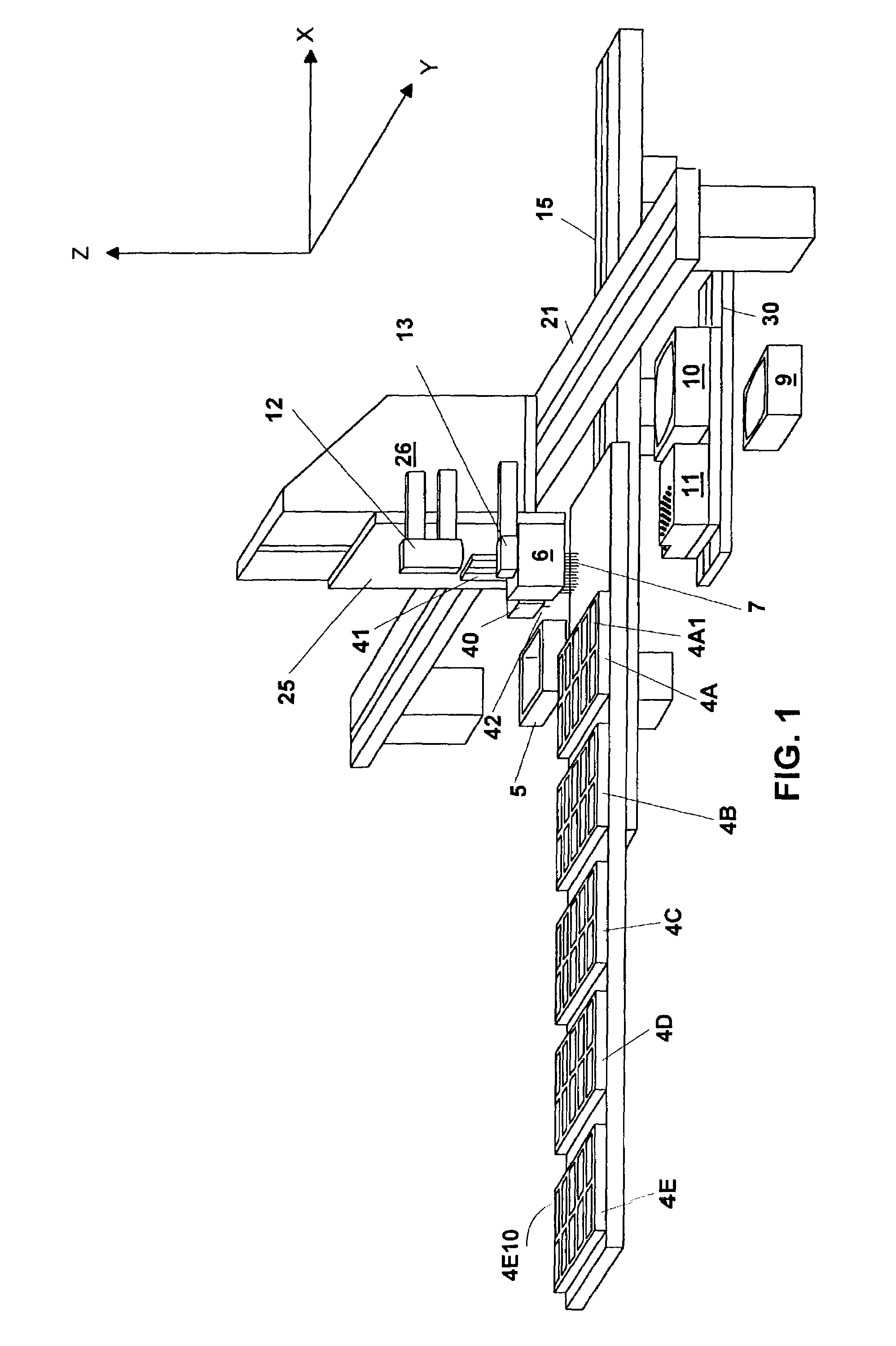
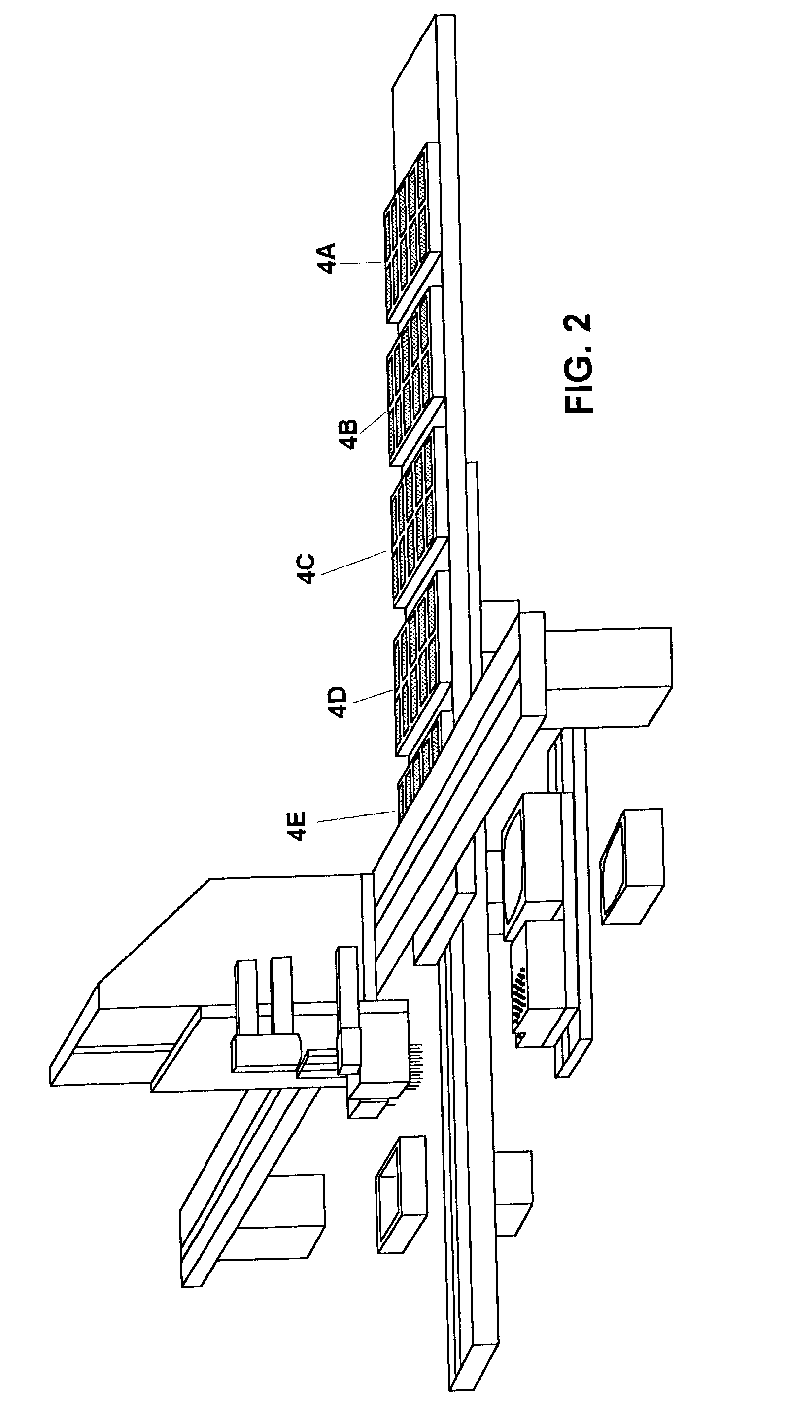
[0104]A third preferred embodiment of the present invention is seen by reference to FIG. 42. FIG. 42 shows a perspective view of microarrayer 250. In the third preferred embodiment, dispense head 202 is connected via mounting plate 213 to linear actuator 214 so that dispense tips 208 can be raised and lowered along the z-axis. Camera 215 and strobe 216 are also mounted to mounting plate 213 and can be raised and lowered along the z-axis by linear actuator 214. Linear actuator 214 is mounted to linear actuator 217 so that it can move along the y-axis.

[0105]Platform 218 is mounted to linear actuator 219 so that it can move along the x-axis. 140 slides 220(1)–220 (140) are mounted on top of platform 218. Microplates 204(A–C) and pre-spot slide holder 205 having pre-spot slide 206 are placed on top of platform 218.

Operation of the Third Preferred Embodiment Removing Solution From the Microplate

[0106]To remove solution from microplate 204(A), linear actuator 219 moves platform 218 along ...


PUM

PropertyMeasurementUnit
travel distanceaaaaaaaaaa

Abstract

A microarrayer for spotting solution onto a receiving surface in an automated microarray dispensing device. Elements of the present invention include: at least one dispense head for spotting the receiving surface, at least one light source capable of illuminating the receiving surface, at least one camera operating in conjunction with the at least one light source. The at least one camera is capable of acquiring and transmitting surface image data to a computer. The computer is programmed to receive the surface image data and analyze it. The computer will then generate post analysis data based on the analysis of the surface image data. The post analysis data is available for improving the spotting of the solution onto the receiving surface. In a preferred embodiment, the surface image data includes information relating to receiving surface alignment, information relating to spot quality, and receiving surface identification information. In a preferred embodiment, the analysis of the information relating to receiving surface alignment enables the computer to make automatic adjustments to the relative positions of the at least one dispense head and the receiving surface to increase the accuracy of the spotting. In a preferred embodiment, the analysis of the information relating to spot quality identifies a spot as pass or fail. An operator is then able to rework the spot. In a preferred embodiment, the analysis of the receiving surface identification information enables the computer to track each receiving surface. In a preferred embodiment the receiving surface is a plurality of slides.

Description

[0001]The present invention relates to automated microarray dispensing devices, more specifically it relates to automated microarray dispensing devices with automated quality inspection capability. This application is a continuation in part application of U.S. patent application Ser. No. 09 / 611,256 filed Jul. 6, 2000, now U.S. Pat. No. 6,558,623, which is incorporated by reference herein.BACKGROUND OF THE INVENTION[0002]Microarrays, also known as biochips, have recently become important in the study of genomics. The use of a microarray involves laying down an ordered array of genetic elements onto a solid substrate such as a slide. Depending on the application, a microarray may consist of genomic DNA, reverse-transcribed cDNA, or smaller chains of oligonucleotides as well as any preparatory substrates. The microarray is useful because it allows genetic analysis to take place on a massively parallel scale, wherein thousands of genes and markers can be scored in one experiment.[0003]A...

Claims


Application Information

Patent Timeline
Patent Type & Authority Patents(United States)
IPC IPC(8): B32B27/04B32B27/12B32B5/02G01N21/00G01N31/00B01J19/00B01L3/00B01L3/02B01L99/00C40B60/14C40B70/00G01N1/00G01N1/10G01N1/31G01N15/06G01N21/29G01N21/41G01N21/47G01N31/22G01N33/00G01N33/48G01N35/00G01N35/10G06F
CPCB01J19/0046B01L3/0244G01N1/312G01N35/1074G01N2035/1034B01J2219/00378B01J2219/00387B01J2219/00475B01J2219/00527B01J2219/00529B01J2219/00549B01J2219/00576B01J2219/00585B01J2219/0059B01J2219/00596B01J2219/00605B01J2219/00608B01J2219/00612B01J2219/00621B01J2219/00637B01J2219/00641B01J2219/00659B01J2219/00689B01J2219/00691B01J2219/00693B01J2219/00695B01J2219/00698B01J2219/00722B01L3/0241B01L9/52C40B60/14C40B70/00G01N2035/00158B01J2219/00351B01L13/02
Inventor GANZ, BRIAN L.MICKLEY, MANDEL W.MOULDS, JOHN ANDREWBROVOLD, CHRISTOPHER T.
Owner AGENA BIOSCI
Why Eureka
Try Eureka