Power measurement system

a technology of power measurement system and sensor, which is applied in the direction of power measurement by thermal methods, electric devices, instruments, etc., can solve the problems of inability to measurement errors can arise, and the cal’ solution of power measurement system cannot allow user-calibration changes of cables, so as to improve the accuracy and user convenience of instrumentation, and improve the verification of the correct operation of the sensing element. , the effect of increasing measurement confiden

Active Publication Date: 2006-04-11
KEYSIGHT TECH
View PDF5 Cites 43 Cited by
  • Summary
  • Abstract
  • Description
  • Claims
  • Application Information

AI Technical Summary

Benefits of technology

[0025]It is thus possible to provide a sensor unit apparatus, a power measurement system and a method of maintaining accuracy of the power measurement system that provide increased measurement confidence, instrumentation accuracy and user convenience and allow accurate DC path gain calculation to take place on a per meter unit basis. The provision of an in-built reference signal that can be switched into the measurement path to establish the path gain allows path gain calibration to be carried out as an automated procedure controlled by the meter unit in a manner completely transparent to a user. The path gain calibration is also independently verifiable with a degree of accuracy not afforded by current systems and methods. The ability to switch a reference signal into the measurement path in order to provide sensing element stimulus also permits verification of correct operation of the sensing element from a response by the sensing element to the reference signal stimulus. By varying the reference signal stimulus, a more sensitive indication of the transfer characteristics of the sensing element, and hence an improved verification of the correct operation of the sensing element, can be achieved than by current systems and methods. It is thus possible to verify that the sensor uni

Problems solved by technology

During this partly manual procedure, measurement errors can arise if the reference source is not mechanically connected efficiently to the sensor unit.
Further, the user calibration procedure is inconvenient and relies on an RF source, with associated mismatch uncertainties, to measure what is predominantly a DC circuit (referred to here as the path gain calibration).
It therefore follows that the above ‘no-cal’ solution for power measurement systems is not capable of allowing chang

Method used


Image

  • Power measurement system
  • Power measurement system
  • Power measurement system

Examples


Embodiment Construction

[0033]Throughout the following description, identical reference numerals will be used to identify like parts.

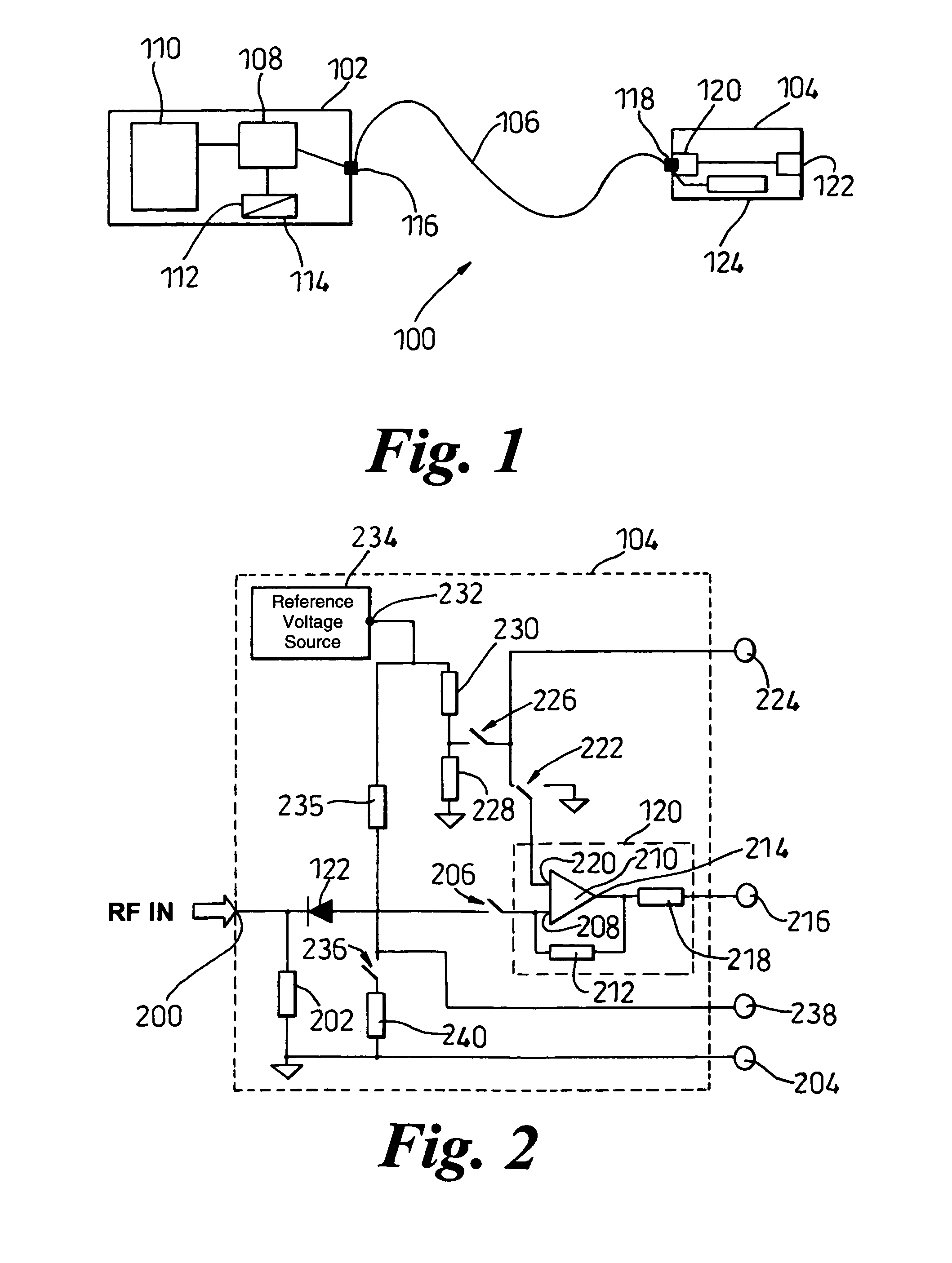
[0034]Referring to FIG. 1, a power measurement system 100 comprises a meter unit 102 coupled to a sensor unit 104 via a cable 106. The meter unit 102 comprises a microprocessor 108 coupled to a display 110, a volatile memory 112, for example a Random Access Memory (RAM), and a non-volatile memory 114, for example a Read Only Memory (ROM).

[0035]The meter unit 102 also comprises an input / output port 116 to which a first end of the cable 106 is coupled. The meter unit 102 is a meter unit designed to work with specific types of sensor units and cables.

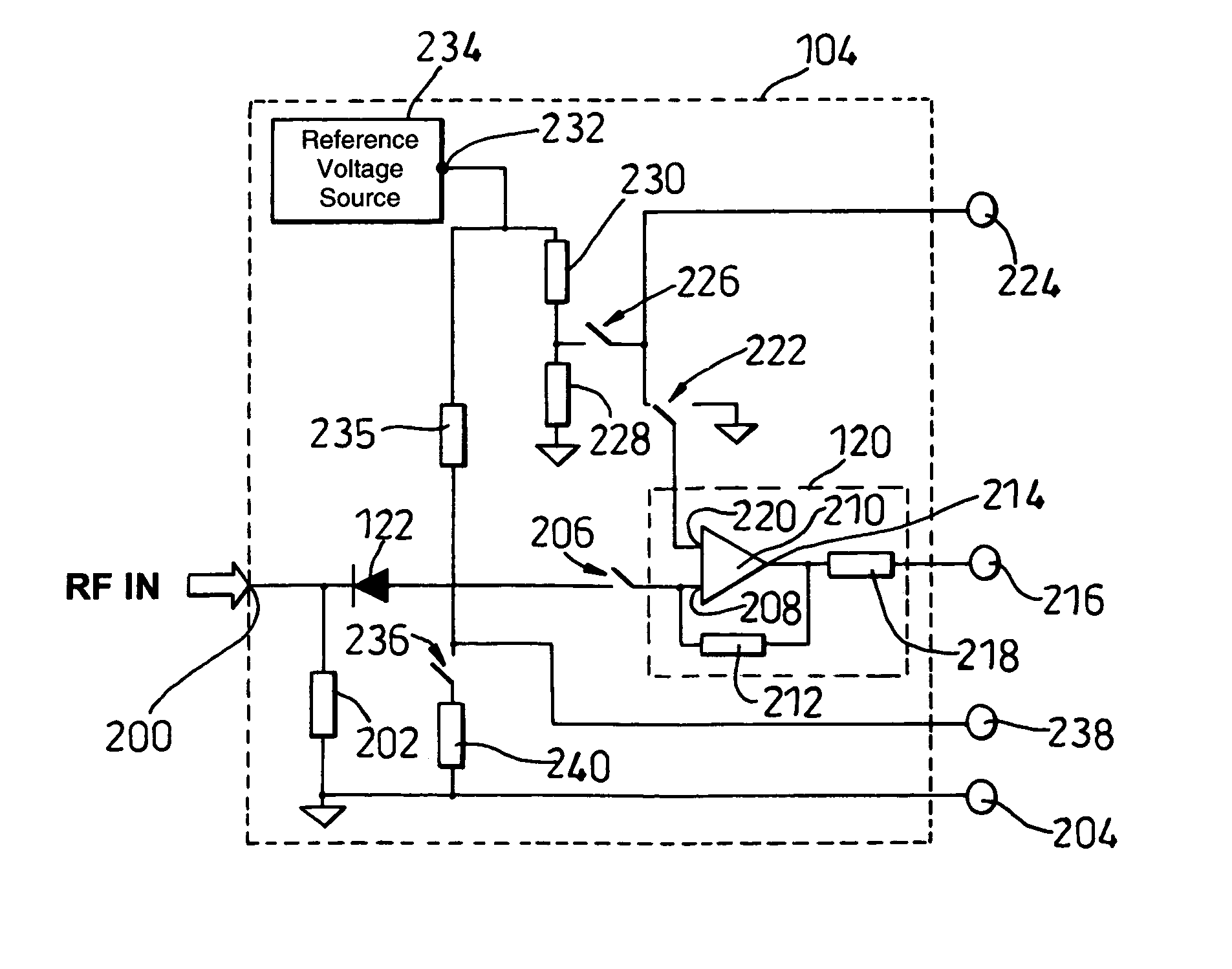
[0036]The sensor unit 104 comprises an output port 118 having a plurality of terminals. One of the plurality of terminals is a detected signal output pin (not shown in FIG. 1) coupled to an amplification circuit 120, the amplification circuit 120 being coupled to a sensor 122, for example, a zero biased diode. An EEPROM 124 is also ...


PUM


Abstract

A power meter is provided in which calibration is carried out as an automated procedure controlled by the meter.

Description

TECHNICAL FIELD[0001]The present invention relates to a power meter and sensor apparatus of the type used, for example, in a system for measuring the power of Radio Frequency (RF) signals. In particular the present invention relates to a system for measuring the power of RF signals that offers increased measurement confidence and instrumentation accuracy in a manner that is convenient to the user of the system.BACKGROUND ART[0002]Standard RF power measuring systems used for testing RF equipment during manufacture, installation and maintenance comprise a meter unit coupled to a sensor unit by a cable. Typically, the sensor unit comprises a sensing element that converts RF power to an equivalent voltage or current signal. The sensing element is typically a diode or a thermocouple. The voltage or current signal can be amplified and conditioned, for example, so that the meter unit can provide an indication of power.[0003]In order to ensure measurement traceabilty to national standards, ...

Claims


Application Information

Patent Timeline
IPC IPC(8): G01R31/00G01R21/02G01R21/10G01R21/14G01R35/00
CPCG01R35/005G01R21/14G01R21/02G01R21/10
Inventor ANDERSON, ALANBREAKENRIDGE, ERIC
Owner KEYSIGHT TECH
Why Eureka
Try Eureka