Current detector and wattmeter using the same

a current detector and wattmeter technology, applied in voltage/current isolation, measurement using dc-ac conversion, instruments, etc., can solve the problems of high cost, inaccurate measurement of current detector magnitude, and increase in size of current detector, so as to improve detection sensitivity, small and inexpensive configuration, and accurate performance

Inactive Publication Date: 2012-07-10
TOSHIBA TOKO METER SYST
View PDF14 Cites 21 Cited by
  • Summary
  • Abstract
  • Description
  • Claims
  • Application Information

AI Technical Summary

Benefits of technology

[0006]In addition, providing the ferromagnetic body in the current detector and increasing the number of turns of a coil in order to improve detection sensitivity may cause the current detector to increase in size and result in a high cost.
[0007]The present invention has been made in order to solve the above-mentioned problems. An object of the present invention is to provide a small and inexpensive current detector and a wattmeter using the current detector that can measure a magnitude of current accurately.
[0009]According to the current detector of the first aspect of the present invention, a density of a magnetic flux is high and uniform in a magnetic sensing surface of the magneto-electric transducer since the length of the magneto-electric transducer in the magnetic sensing axis direction is much shorter than the width of an upper conductor and a lower conductor of the conductor. Therefore, the detection sensitivity is improved compared with the conventional current detector. Accordingly, the accurate measurement of the current can be achieved. Moreover, the small current detector can be manufactured inexpensively.
[0013]Due to such a configuration, the detection sensitivity is improved, and the current detector is not influenced by an external magnetic field.
[0015]Due to such a configuration, mutual interference between the magneto-electric transducers can be eliminated, thereby improving detection sensitivity.
[0017]The wattmeter according to the third aspect of the present invention uses the current detector according to the first aspect of the present invention. Accordingly, detection sensitivity can be improved compared with the conventional current detector, a measurement of current can be performed accurately, and a small and inexpensive configuration can be achieved.

Problems solved by technology

However, the conventional current detector may not measure a magnitude of current accurately because of mutual interference of magnetic fields generated by current to be detected flowing in conductors adjacent to each other, an influence of an external noise, and a shift in position of the magneto-electric transducer over time, for example.
In addition, providing the ferromagnetic body in the current detector and increasing the number of turns of a coil in order to improve detection sensitivity may cause the current detector to increase in size and result in a high cost.

Method used


Image

  • Current detector and wattmeter using the same
  • Current detector and wattmeter using the same
  • Current detector and wattmeter using the same

Examples


example 1

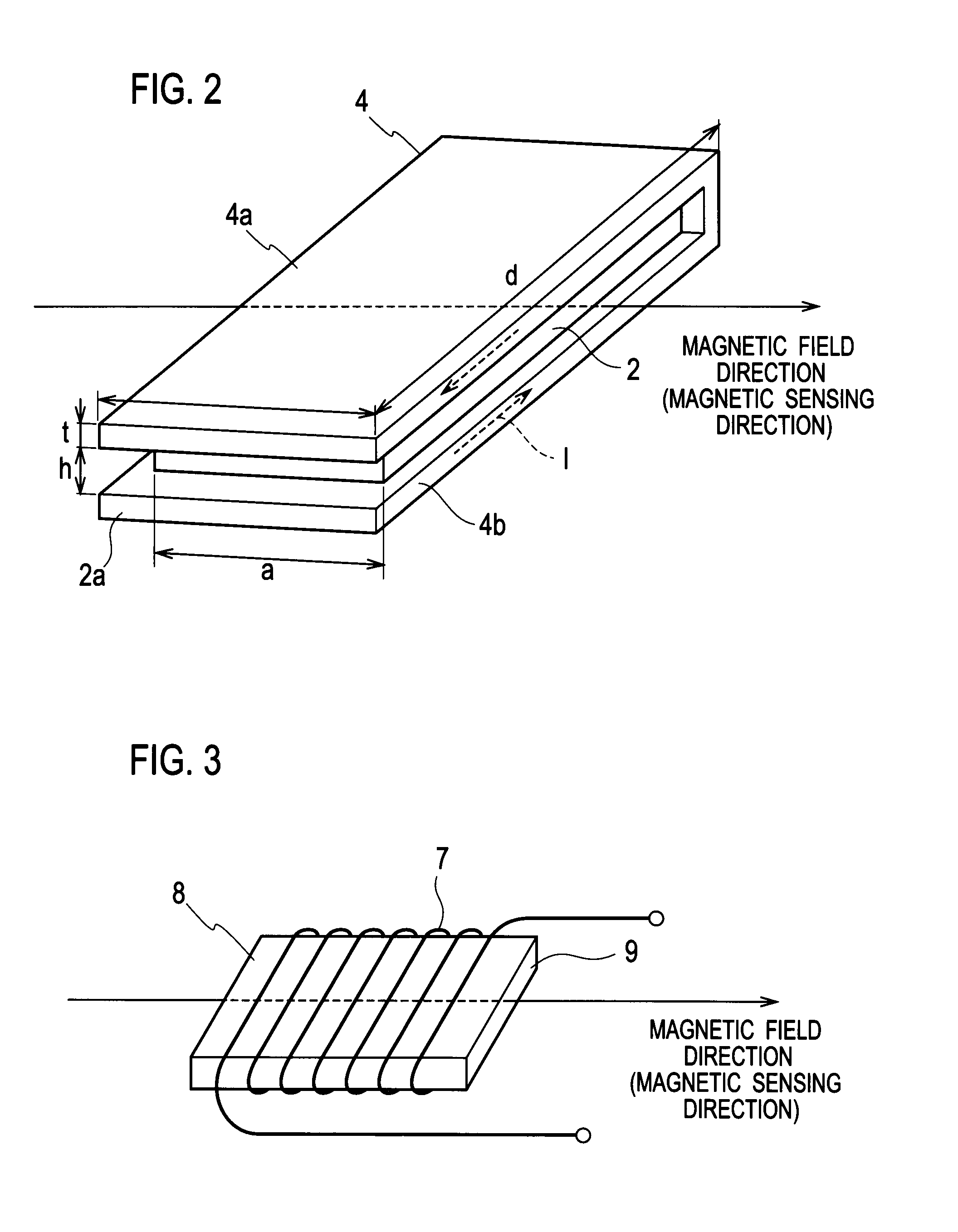
[0030]A current detector according to Example 1 of the present invention illustrated in FIG. 2 includes a plate-like conductor 4 having a predetermined width w1 is folded approximately in the middle in a longitudinal direction so as to have an upper conductor 4a and a lower conductor 4b parallel to and facing each other having a gap h therebetween. Thus, a current path 2a formed into a loop (hereinafter, referred to as a looped current path) is obtained in the conductor 4. Alternatively, a method of cutting in the conductor 4 may be used to form the looped current path.

[0031]A magneto-electric transducer 2 is placed in a center portion in the gap between the upper conductor 4a and the lower conductor 4b, namely in a center portion of the looped current path 2a. The magneto-electric transducer 2 is to have detection sensitivity with respect to a direction of a magnetic field (a right direction in FIG. 2) that is generated by a flow of the current to be detected I in the looped curren...

example 2

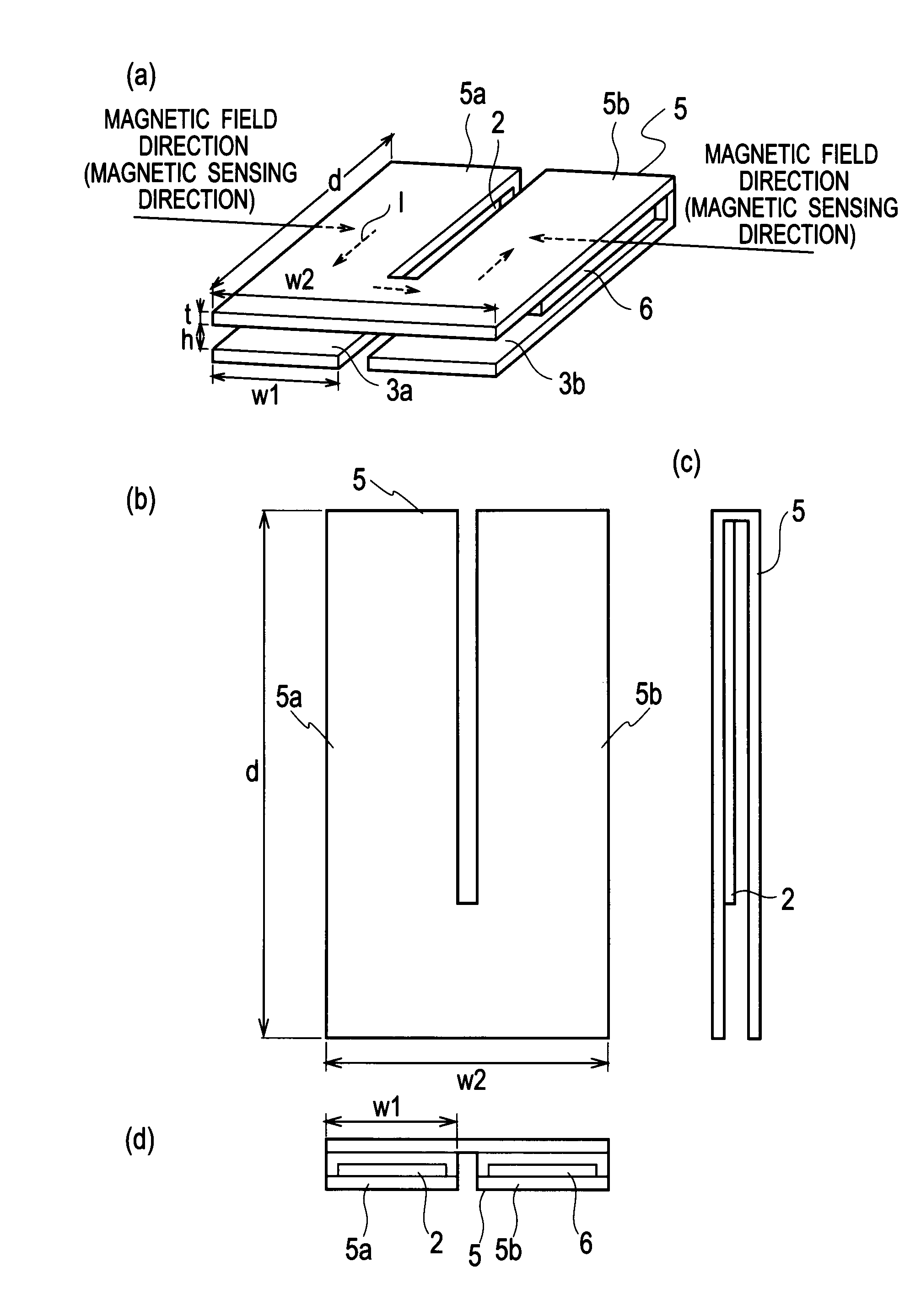
[0043]FIG. 9 illustrates a configuration of a current detector according to Example 2 of the present invention. FIG. 9(a) is an external perspective view, FIG. 9(b) is a plan view, FIG. 9(c) is a side view, and FIG. 9(d) is a front view. The current detector according to Example 2 of the present invention illustrated in FIG. 2 includes a U-shaped plate-like conductor 5 having a predetermined width w2. The conductor 5 is folded approximately in the middle in a longitudinal direction so as to have an upper conductor and a lower conductor parallel to and facing each other having the gap h therebetween. Thus, a first looped current path 3a is formed in a first conductor 5a having a predetermined width w1. Similarly, a second looped current path 3b is formed in a second conductor 5b having the predetermined width w1.

[0044]The U-shaped plate-like conductor 5 is folded in half so as to form the first conductor 5a and the second conductor 5b, which are connected with each other at a bottom ...


PUM


Abstract

A current detector includes a plate conductor (4) that is folded in one portion in a longitudinal direction to have two parts parallel to and facing each other having a predetermined width (w1) therebetween, so as to compose a looped current path (2a) in the conductor, and a magneto-electric transducer (2) that is placed between the two parts of the conductor (4; 4a, 4b) so that a magnetic sensing axis is parallel to a width direction of the conductor (4), of which a length (a) in a direction of the magnetic sensing axis is smaller than the width (w1) of the conductor.

Description

TECHNICAL FIELD[0001]The present invention relates to a current detector for detecting a magnitude of current flowing in a conductor due to magneto-electric conversion, and also relates to a wattmeter using the current detector.BACKGROUND ART[0002]In a conventional electric wattmeter, a current detector including a magneto-electric transducer as illustrated in FIG. 1 is used in a current measurement unit (see PTL 1). The current detector includes a conductor 1 to form a looped current path 1b, a magneto-electric transducer 2 provided in the center of the looped current path 1b so as to pass a magnetic flux F therethrough, in which the magnetic flux F is generated by a current to be detected I flowing in the current path 1b, and a ferromagnetic body 3 for collecting the magnetic flux F around the magneto-electric transducer 2.[0003]The configuration of the current detector is simple, and a method of fixing the magneto-electric transducer to the current detector is not complicated. Th...

Claims


Application Information

Patent Timeline
Patent Type & Authority Patents(United States)
IPC IPC(8): G01R33/07
CPCG01R15/207G01R21/08
Inventor KUROKI, YUTAKUROKAWA, FUYUKISAKOYAMA, MITSUHIRO
Owner TOSHIBA TOKO METER SYST
Why Eureka
Try Eureka